Operation
2.2 Connection to the
System
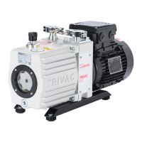
Before connecting the TRIVAC B, remove the shipping
seals from the connection flanges (7/2) and (7/3).
Retain the shipping seals in case you need
to store the pump in the future.
The pump is shipped with intake and exhaust flanges
mounted for horizontal connection of the connecting
lines. You can easily convert the ports for vertical
connection by removing the four capscrews, rotating the
flanges as required, and reinstalling the capscrews.
Connect the intake and exhaust lines with a centering
ring and a clamping ring each. Use the centering ring
with dirt trap for the intake port.
Connect the intake and exhaust line using anti-vibration
bellows, without placing any strain on the pump.
The intake line must be clean. Deposits in
the intake line may outgas and adversely
affect the vacuum. The connecting flanges
must be clean and undamaged.
The maximum throughput of the pump is
equivalent to the pumping speed of the
pump (see Section 1.6).
The cross-section of the intake and exhaust
lines should be at least the same size as
the connection ports of the pump. If the
intake line is too narrow, it reduces the
pumping speed. If the exhaust line is too
narrow, overpressures may occur in the
pump; this might damage the shaft seals
and cause oil leaks.
The maximum pressure in the oil case must
not exceed 1.5 bar (absolute).
When pumping vapours, it is advisable to
install condensate traps on the intake and
exhaust sides.
Install the exhaust line with a downward
slope (lower than the pump) so as to
prevent condensate from flowing back into
the pump. If this is not possible, insert a
condensate trap.
In order to reduce the emission of oil
vapours we recommend the installation of
an additional exhaust filter.
Depending on the type of application or the
kind of pumped media, the corresponding
regulations and information sheets must be
observed.
The pumps may be operated with an inert gas ballast via
a connection which is provided for this purpose. The
cover plate (7/8) can be removed to gain access to this
M 16 x 1.5 threaded port (7/6). Matching connectors are
available (see Section 1.3).
The inlet pressure for the gas ballast should be about
1000 mbar (absolute) and sufficient quantities of gas
must be available (about
1
/
10
of the pumping speed).
Never operate the pump with a sealed
exhaust line. There is the danger of injury.
Before starting any work on the pump, the
personnel must be informed about possible
dangers first. All safety regulations must be
observed.
10
Caution
Warning
Caution
Caution
 Loading...
