1.1 Function
The rotor (2/7), mounted eccentrically in the pump
housing (2/6), has two radially sliding vanes (2/5) which
divide the pump chamber into several compartments.
The volume of each compartment changes periodically
with the rotation of the rotor.
As a result, gas is sucked in at the intake port (2/1). The
gas passes through the dirt trap sieve (2/2), flows past
the open anti-suckback valve (2/3) and then enters the
pump chamber. In the pump chamber, the gas is passed
on and compressed, after the inlet aperture is closed by
the vane.
The oil injected into the pump chamber is used for
sealing and lubricating. The slap noise of the oil in the
pump which usually occurs when attaining the ultimate
pressure is prevented by admitting a very small amount
of air into the pump chamber.
The compressed gas in the pump chamber is ejected
through the exhaust valve (2/10). The oil entrained in the
gas is coarsely trapped in the internal demister (2/11);
there the oil is also freed of mechanical impurities. The
gas leaves the TRIVAC B through the exhaust port.
Description
During compression, a controlled amount of air – the so-
called gas ballast – can be allowed to enter the pump
chamber by opening the gas ballast valve. The gas
ballast stops condensation of vapours in the pump
chamber up to the limit of the water vapour tolerance as
specified in the technical data for the pump.
The gas ballast valve is opened and closed by turning
the gas ballast knob (7/5) on the front.
To enable the TRIVAC B to be used at intake pressures
as high as 1,000 mbar, a special lubricating system was
developed featuring force-lubrication of the sliding
bearings.
An oil pump (3/6) pumps the oil from the oil reservoir
(3/5) into a pressure-lubrication system which supplies
oil to all bearing points (3/2). From there the oil enters the
pump chamber area (3/4) of the vacuum pump.
The oil pump is fitted in the front end plate on the
coupling side of the pump module. The oil suction line is
placed low, resulting in a large usable oil reservoir.
4
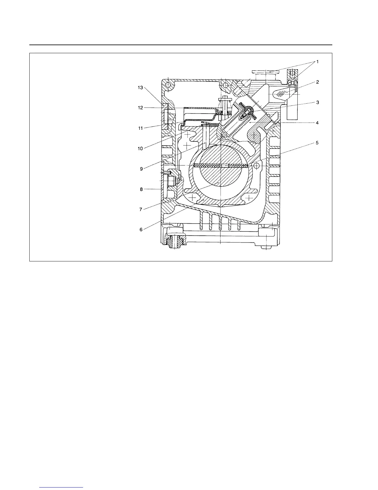
Fig. 2 Sectional drawing of the TRIVAC B
Key to Fig. 2
1 Intake port
2 Dirt trap
3 Anti-suckback valve
4 Intake channel
5 Vanes
6 Pump chamber
7 Rotor
8 Cover plate, connection for inert gas ballast
9 Exhaust channel
10 Exhaust valve
11 Internal demister
12 Spring buckles
13 Cover plate, connection for oil filter

 Loading...