- 12 -
LGE Internal Use OnlyCopyright ©2010 LG Electronics Inc. All rights reserved.
Only for training and service purposes
6. HDCP(High-Bandwidth Digital
Contents Protection) Download
HDCP download process is deleted in PP01A/B/C Chassis
In PP01A/B/C Chassis, it is usi
g the EEPROM masking
HDCP Key
7. Manual ADC Adjustment
(Component 1, RGB)
Caution
- Do not connect external input cable
- Adjustment result is applied to SET On/Off later.
* Adjustment is done using internal ADC, so input signal is not
necessary.
7-1. COMPONENT input ADC (SD / HD),
RGB input ADC
(1) Press ADJ key on R/C for adjustment. Need not convert
input mode.
(2) Enter Password number. The value of Password is “0 0 0
0”.
(3) Select “0. ADC calibration” by using D/E(CH +/-) and press
ENTER(V).
(4) Start ADC adjustment by using F/G(VOL +/-) or press
ENTER(V).
(5) Both component and RGB ADC adjustment are executed
automatically
When ADC adjustment is finished, this OSD appear.
Notice : After All mode check, set the Speaker Volume “0”.
Caution : Don’t Press the Power Key on Remote Controller.
Just AC Power Off. ( Not DC off )
Notice : From this sentence, All working is mass production.
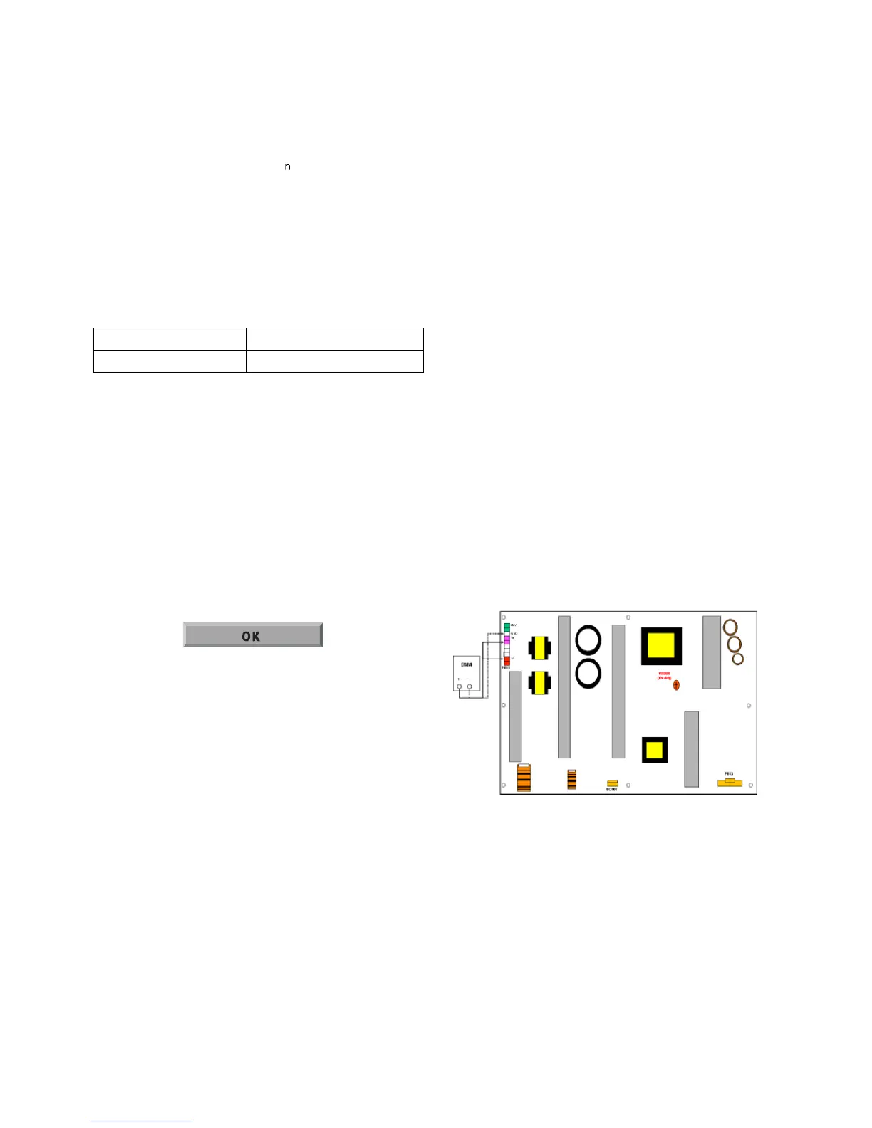
8. POWER PCB Assy Voltage
Adjustment
(Vs voltage Adjustment)
8-1. Test Equipment: D.M.M 1EA
8-2. Connection Diagram for Measuring
Refer to (Fig. 4)
8-3. Adjustment Method
(1) Vs Adjustment
1) Connect + terminal of D. M..M. to Vs pin of P811,
connect -terminal to GND pin of P811.
2) After turning VR901, voltage of D.M.M adjustment as
same as Vs voltage which on label of panel right/top
( deviation ; ±0.5V)
(2) Va Adjustment
1) Connect + terminal of D. M..M. to Va pin of P811,
connect -terminal to GND pin of P811.
2) After turning VR502, voltage of D.M.M adjustment as
same as Va voltage which on label of panel right/top
( deviation ; ±0.5V)
RF input
NO SIGNAL or White noise
AV / Component / RGB input
NO SIGNAL
(Fig. 4)
 Loading...