22
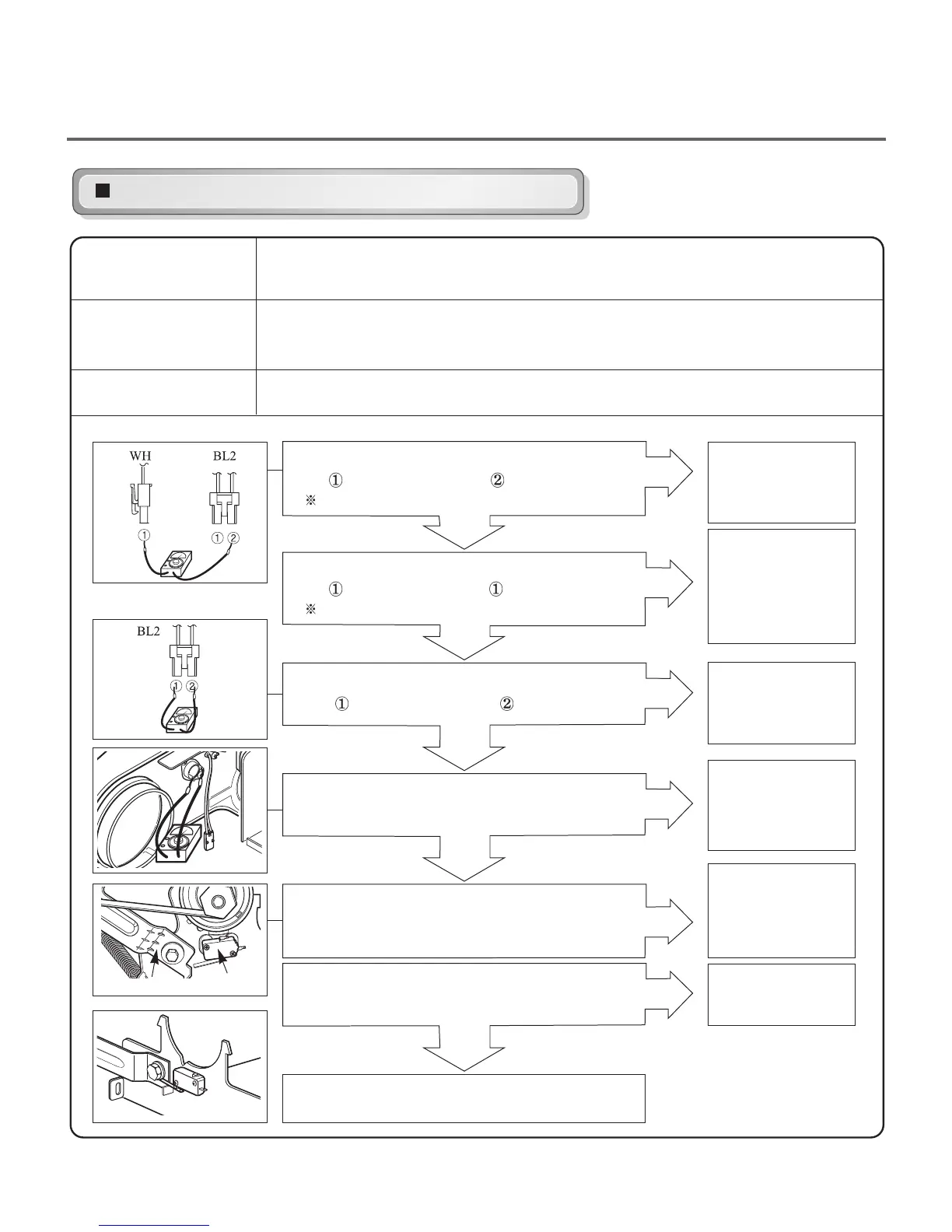
Before measuring resistance, be sure to turn power off, and do voltage discharge.
(When discharging, contact the metal plug of power cord with earth line.)
Drum will not rotate; no fan will function; no heater will work.
Turn the dryer’s power off, then measure resistance.
Test 3
Motor test
Caution
Trouble Symptom
Measurement Condition
1
Is resistance below 1Ω between Idler Switch
terminals?
YES
NO
Does Idle Switch attached to Motor Bracket
operate Level by drum belt?
(Not operating Lever is normal.)
YES
• Replace Idler
Switch.
• Check Idler Assembly.
• Drum Belt cuts off
• Drum Belt takes off
from Motor Pulley.
Is resistance below 3Ω between Connector
WH
(White wire) and BL2- (Yellow wire)?
Measure while door is closed.
YES
NO
• Check if Door flame
presses door switch
knob.
• Check Door Switch.
• Check Harness
connection.
Is resistance below 3Ω between Connector
BL2-
(Yellow wire) and BL2- (Brown wire)?
NO
YES
• Replace Control.
(Relay check)
• Check Controller
connector.
Is resistance below 1Ω between terminals
of Outlet Thermostat attached to blower housing?
YES
NO
• Replace Outlet
• Thermostat.
(Refer to
‘Component’)
Is resistance below 3Ω between Connector
WH
(White wire) and BL2- (Brown wire)?
Measure while door is closed.
NO
YES
• Replace Control.
(Relay check)
• Check Controller
connector.
• Check Motor.
(Refer to ‘Motor Diagram & Check’)
•
Check if Control Connector is contacted.
Idler Switch Lever
Idler Switch
 Loading...