 Loading...
Do you have a question about the LG WM2277HW and is the answer not in the manual?
| Type | Front Load Washer |
|---|---|
| Energy Star | Yes |
| Color | White |
| Height | 39 inches |
| Steam Washer | Yes |
| Voltage | 120 V |
| Spin Speed | 1200 RPM |
Lists key features: Direct Drive, Tilted Drum, Water Circulation, RollerJets, Load Detection, Heater, Child Lock, RLM.
Explains how Neuro Fuzzy logic optimizes wash time based on temperature and load size.
Describes the pressure sensor for water level detection and control.
Explains door operation, locking, unlocking after power failure, and associated sounds.
Lists specific conditions under which the washing machine door remains locked.
Explains the conditions that activate the door locked indicator lamp.
Details how to activate and use the Child Lock feature to prevent unintended operation.
Describes the water circulation process during washing and rinsing cycles.
Provides steps for standard installation, including removing transit bolts and leveling the appliance.
Instructions for securely connecting the water inlet hoses to prevent leaks.
Guidelines for connecting the drain hose, ensuring it's not twisted or submerged.
Instructions for safely connecting the power plug to the wall outlet.
Explains usage of Power, Est. Time, Child Lock, Cycle Selector, Start/Pause, and Custom Program buttons.
Details the function and delay range of the Delay Wash button.
Explains the meaning of the status indicator lights during the wash cycle.
Describes when the door locked lamp is active and how to unlock the door.
Details selecting water temp, spin speed, soil level, and adjusting beeper volume.
Explains options like Prewash, Rinse+Spin, Extra Rinse, Stain Cycle, Quick Cycle.
Safety precautions and checks before starting any troubleshooting procedures.
Detailed steps to enter and operate the Quality Control (QC) Test Mode.
Method to check water level frequency using specific button combinations.
Lists common error codes, their symptoms, and potential causes for troubleshooting.
Flowcharts guide users through diagnosing and resolving abnormal operation symptoms.
Provides structured diagnostic procedures and solutions for various operational faults.
Troubleshooting steps for addressing excessive vibration and noise during the spin cycle.
Troubleshooting guide for issues related to the washing machine not receiving water.
Troubleshooting steps for problems where detergent is not flowing into the dispenser correctly.
Diagnosis and solutions for heating problems occurring when no water is supplied.
Troubleshooting steps for issues specifically related to the wash heater component.
Addresses problems where the water temperature remains higher than the selected setting.
Troubleshooting guide for situations where the water circulation system is not functioning.
Diagnostic steps for problems occurring during the washing machine's spin cycle.
Troubleshooting for general error states, focusing on door latch and switch issues.
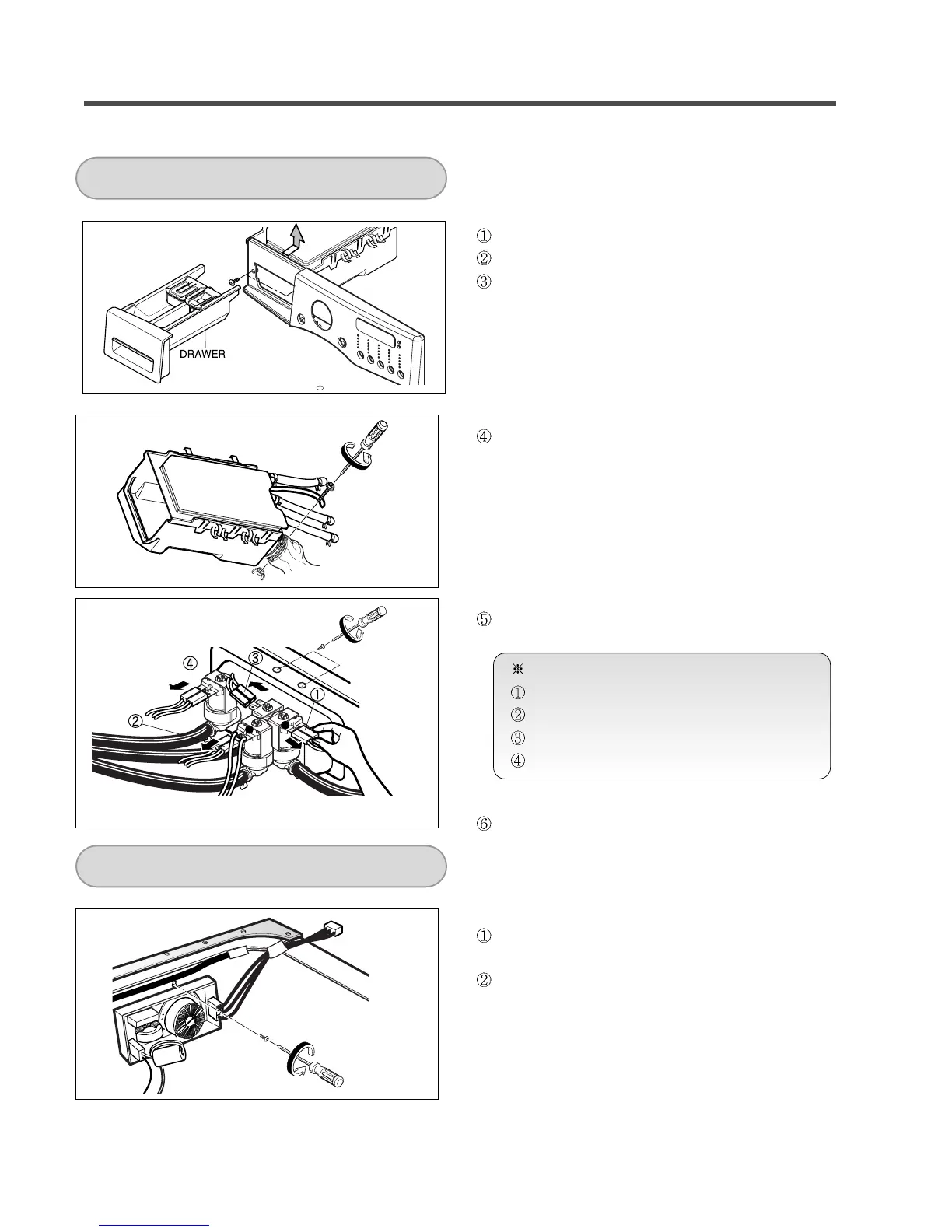
Step-by-step guide for safely disassembling the washing machine's control panel.
Instructions for disassembling the Main Printed Wiring Board (PWB) assembly.
Steps for disassembling the detergent dispenser assembly and its components.
Instructions for disassembling the noise filter component.
Detailed instructions for safely removing the washing machine's cabinet cover.
Steps for disassembling and removing the washing machine door.
Instructions for disassembling the door lock switch assembly.
Steps for disassembling the water pump assembly.
Instructions for disassembling the water heater component.
Steps for disassembling and removing the thermistor.
Guide for removing foreign objects lodged between the drum and tub.
Instructions for disassembling the ball sensor assembly.
Steps for disassembling the motor and damper components.
Exploded view illustrating the cabinet and control panel assembly components.
Exploded view illustrating the drum and tub assembly components.
Exploded view illustrating the dispenser assembly components.