4
lci1.com 574-537-8900 CCD-0001533 Rev: 06.29.18
Level Up
™
Installation and Owner’s Manual
(For Aftermarket Application)
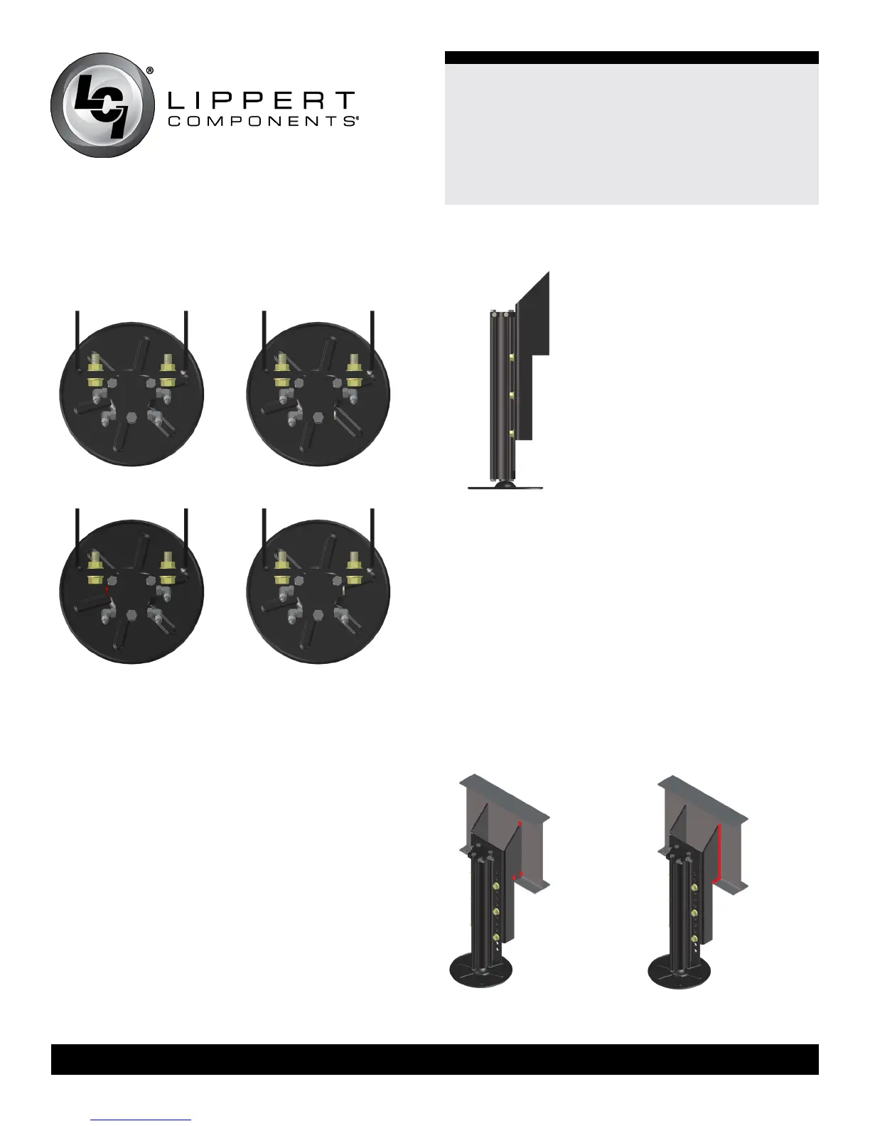
4. Install hydraulic ttings to leveling jacks. See (Figs.4-7)
for details of tting placement. This example assumes the
power unit is closest to the driver’s side (roadside) of the
trailer.
5. If no modications to the jack brackets are necessary,
skip to Step 9.
6. Dry t the jack brackets to the chassis of the trailer
frame. The rear jacks must be mounted within the
departure angle, should be aligned with each other from
side to side, mounted 12”-18” behind the rear tires on a
tandem axle trailer or as close to the rear tire, as allowed,
on a tri-axle trailer. The mid jacks should be mounted
approximately 1 foot in front of the front tires. The mid jacks
can be oset from each other side to side by up to 24” in
order to t the jacks around steps or other obstructions.
The universal mounting brackets are designed to t a
12” I-Beam with no modications. However, the frame on
the trailer may not be 12” or there may be obstructions
where the jacks are to be mounted. If that is the case,
measure for the modications you need to make to the jack
brackets.
Fig.4 Fig.5
Fig.6 Fig.7
7. Mark the needed modications on the jack brackets
(Fig.8).
8. Using a cutting torch or plasma cutter, cut the material
from the bracket, being careful not to damage the leveling
jack or ttings attached to it.
9. Fit the mounting bracket against the I-Beam, making
sure that the bottom edge of the mounting ange is ush
with the bottom lip of the I-Beam.
10. Tack weld the top and bottom corners of each side of
the mounting ange (Fig.9).
11. By implementing a
¼” weld bead, fully weld the bracket
to the I-Beam from top to bottom on both sides of the
bracket (Fig.10). Make sure to avoid any hoses or wiring
that may be in the welding area.
Fig.8
Fig.9
Fig.10
 Loading...