7
lci1.com 574-537-8900 CCD-0001533 Rev: 06.29.18
Level Up
™
Installation and Owner’s Manual
(For Aftermarket Application)
Assembling and Mounting the Valve Blocks
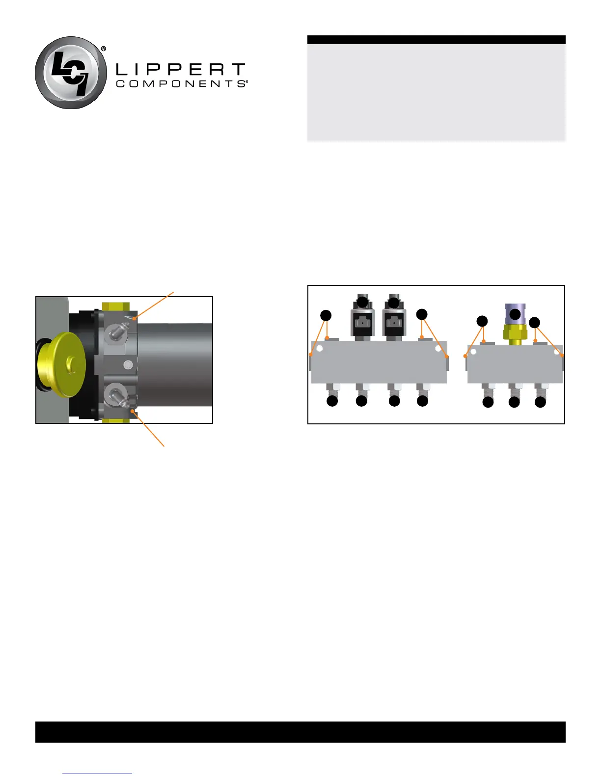
1. Install two valve and coil assemblies in the Extend Valve
block (Fig.20A and 20B) in the two center ports.
2. Install 4 straight JIC (Fig.20F, 20G, 20H and 20I)
adapters into the 4 ports across from the two valves you
previously installed. Install plugs (Fig.20D) (removed from
leveling jacks) into the remaining ports.
3. Install the Pressure Switch (Fig.20C) in the center port
of the retract valve block. Install 3 straight JIC ttings
(Fig.20J, 20K and 20L) into the 3 ports across from the
pressure switch you previously installed. Install plugs
(Fig.20E) (removed from leveling jacks) into the remaining
ports.
4. Cut a piece of
¾” thick plywood into a rectangle large
enough to mount both valve blocks.
Power Unit
1. The power unit mounting location was determined when
the trailer was rst inspected. Mount the power unit to the
back or side wall of the front compartment in the position
you previously determined using six (6) self tapping
screws.
2. Install hose ttings into the power unit (Fig.19).
The two ports are marked DN and UP. DN = Extend.
UP = Retract.
5. Mount the valve blocks to the plywood using 3” screws.
Only drive the screws far enough into the plywood to hold
the valve blocks in place. Do not pierce the back side of
the plywood. Mount the plywood to the back or side wall
of the front compartment next to the pump assembly using
the screws already holding the valve blocks in place.
NOTE: Do not overtighten mounting screws.
Overtightening may deform or damage the valve blocks
causing them to malfunction or leak.
Hydraulic Hoses
1. Connect the rear extend hoses (orange) to the JIC
tting in the extend valve block directly opposite of the two
valves, (Figs.20G and 20H). Orientation is not critical at
this point, the valve coil wires can be switched to correct
the function.
2. Connect the rear retract hose (black) to the JIC tting
in the retract valve block directly across from the pressure
switch, (Fig.20K).
3. Make hoses to connect the power unit to the valve
blocks. 3’ lengths should be sucient; one (1) extend
(orange) hose, and one (1) retract (black) hose.
4. Connect the extend hose to the extend (DN) side of the
power unit, and then to the JIC tting on the extend valve
block closest to the power unit, (Fig.20F).
D
D
B
A
F G H I
E
C
J K L
Extend Valve Block
Retract Valve
Block
Fig.20
Fig.19
up
down
E
 Loading...