8
lci1.com 574-537-8900 CCD-0001533 Rev: 06.29.18
Level Up
™
Installation and Owner’s Manual
(For Aftermarket Application)
5. Connect the retract hose to the retract (UP) side of the
power unit, and then to the JIC tting on the retract valve
block closest to the power unit, (Fig.20J).
6. Make hoses to connect the valve blocks to the lead
landing gear. Six-foot lengths should be sucient; one (1)
extend (orange) hose and one (1) retract (black) hose.
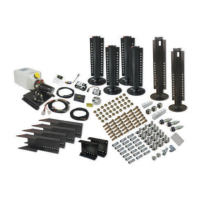
7. Connect the extend hose to the nal JIC tting on the
extend valve block, (Fig.20I) to the JIC tting directly
across from the cartridge valve and coil assembly that is
installed on the lead landing gear, (Fig.21A).
8. Connect the retract hose to the nal JIC tting on the
retract valve block (Fig.20L) to the JIC tting in the retract
port on the lead landing gear (Fig.21D).
9. Make hoses to connect the lead landing gear to the
follow landing gear. Nine-foot lengths should be sucient:
one (1) extend (orange) hose, and one (1) retract (black)
hose.
10. Connect the extend hose to the JIC tting in the rear of
the lead landing gear (Fig.21B) and then to the JIC adapter
in the extend port of the follow landing gear.
11. Connect the retract hose to the JIC tting in the other
retract port of the lead landing gear (Fig.21E) and then to
the tting in the retract port of the follow landing gear.
E
C
D
A
B
Fig.²¹
Wiring the System
NOTE: Refer to the wiring diagram throughout this section.
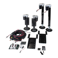
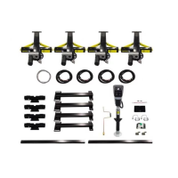
NOTE: The Level Up system wiring is basically a plug and
play system. Your kit should include harnesses for the
entire system. If it does not, contact Lippert Components to
have the proper harnesses shipped to you.
1. Install the controller to the ceiling of the front
compartment. It must be centered side to side, and
oriented according to the arrows on the controller label.
2. Connect the rear sensor harness to the matching port
on the controller.
NOTE: Each connector on the controller is a dierent
shape and has a dierent number of pins. Each harness
that connects to the controller can only be connected in
one specic way. This prevents the installation of the wrong
harness in the wrong connector.
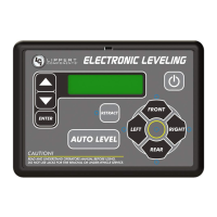
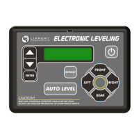
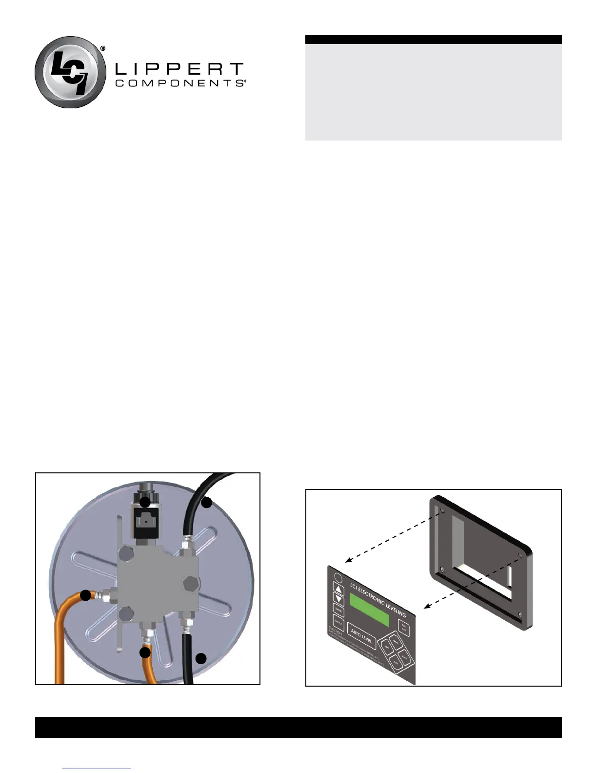
LCD Touch Pad
1. Determine where to mount the touch pad. The touch pad
should be mounted in a compartment on the side of the
unit so the operator will have a view of the hitch pin while
using the touch pad.
2. Remove the face plate of the touch pad from the
mounting bezel (Fig.22).
Fig.²²
 Loading...