43
DATE
22.12.2003
COMPILER TECO/ATI
REG. CODE
1-5302-467
MODEL N°
50707
DATE OF ISSUE
06-95
REVISION 05
ENDORSED
VIII
74 75
73
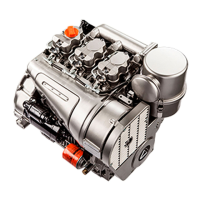
DISASSEMBLY/REASSEMBLY
Dinamic balancer timing
Position crankshaft as shown in the figure.
Introduce the dynamic balancer so that timing mark 1 engages
between teeth 2 of the crankshaft gear.
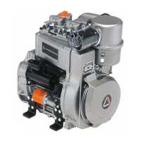
Valve timing check
Remove the tank and conveyor to access the flywheel.
Carry out the inspections on the drive shaft. The values given are
measured on the circumference of the flywheel.
Adjust the valve play as indicated on the next page.
Reset the comparator on the cap of intake valve 1. Turn the drive
shaft in the spinning direction and find
αα
αα
α (point at which the intake
valve starts to open in relation to top dead center A) and
β β
β β
β (point at
which the intake valve shuts after bottom dead center B) see fig. 77-
78.
Proceed in a similar way with the exhaust valve, checking
γγ
γγ
γ (point at
which the exhaust valve opens) and
δδ
δδ
δ (point at which the exhaust
valve shuts).
 Loading...