Operating Instructions Smart Weather Sensor
G. Lufft Mess- und Regeltechnik GmbH, Fellbach, Germany 141
20 List of Figures
Figure 1: Sensor Technology ................................................................................................................................................................. 13
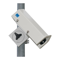
Figure 2: Fastening to the Mast ............................................................................................................................................................. 22
Figure 3: North Markings ....................................................................................................................................................................... 23
Figure 4: Alignment to North .................................................................................................................................................................. 23
Figure 5: Installation Sketch .................................................................................................................................................................. 25
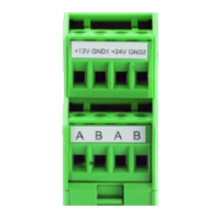
Figure 6: Connections ........................................................................................................................................................................... 26
Figure 7: Connection to ISOCON-UMB ................................................................................................................................................. 28
Figure 8: Sensor Selection .................................................................................................................................................................... 30
Figure 9: General Settings ..................................................................................................................................................................... 31
Figure 10: Temperature, Humidity and Fan Settings .............................................................................................................................. 31
Figure 11: Pressure Settings ................................................................................................................................................................. 32
Figure 12: Wind Settings ....................................................................................................................................................................... 32
Figure 13: Precipitation Sensor Settings (Radar) ................................................................................................................................... 33
Figure 14: Precipitation Sensor Settings (Rain Gauge) .......................................................................................................................... 33
Figure 15: Global Radiation Settings ..................................................................................................................................................... 34
Figure 16: Lightning Sensor Settings ..................................................................................................................................................... 34
Figure 17: Energy Management Settings ............................................................................................................................................... 34
Figure 18: Reset Precipitation Quantity ................................................................................................................................................. 35
Figure 19 Measurement Polling Channels ............................................................................................................................................. 36
Figure 20 Example of Measurement Polling .......................................................................................................................................... 36
Figure 21: Operating Modes for Equipment Heating .............................................................................................................................. 39
Figure 22: WS601-UMB with removed funnel ........................................................................................................................................ 42
Figure 23: WS200-UMB ........................................................................................................................................................................ 48
Figure 24: WS300-UMB ........................................................................................................................................................................ 48
Figure 25: WS301-UMB ........................................................................................................................................................................ 49
Figure 26: WS310-UMB ........................................................................................................................................................................ 50
Figure 27: WS400-UMB ........................................................................................................................................................................ 51
Figure 28: WS401-UMB ........................................................................................................................................................................ 52
Figure 29: WS500-UMB ........................................................................................................................................................................ 53
Figure 30: WS501-UMB ........................................................................................................................................................................ 54
Figure 31: WS510-UMB ........................................................................................................................................................................ 55
Figure 32: WS600-UMB ........................................................................................................................................................................ 56
Figure 33: WS601-UMB ........................................................................................................................................................................ 57
Figure 34: WS700-UMB, WS800-UMB .................................................................................................................................................. 58
Figure 35: Connection of the Leaf Wetness Sensor ............................................................................................................................... 62
Figure 36: Setting the Leaf Wetness Threshold ..................................................................................................................................... 63
Figure 37: Setting type of external sensor.............................................................................................................................................. 64
Figure 38: Example WS501-UMB and WTB100 .................................................................................................................................... 65
Figure 39: Sensor Configuration SDI-12 ................................................................................................................................................ 78
Figure 40: Sensor Configuration SDI-12 Units ....................................................................................................................................... 78
Figure. 41: Connecting to a logger with integrated power supply ........................................................................................................... 79
Figure. 42: Connecting to a logger and a separate power supply up to device version 41 ................................................................... 79
Figure. 43: Connecting to a logger and a separate power supply device version 42 and newer .......................................................... 79
Figure 44: Sensor Configuration XDR .................................................................................................................................................. 129
 Loading...