Operating Manual Smart Weather Sensor
G. Lufft Mess- und Regeltechnik GmbH, Fellbach, Germany 69
19.3 Communication in Binary Protocol
Only one example of an online data request is described in this operating manual. Please
refer to the current version of the UMB Protocol for all commands and the exact mode of
operation of the protocol (available for download at www.lufft.com).
Note: Communication with the sensor takes place in accordance with the master-slave
principle, i.e. there may only be ONE requesting unit on a network.
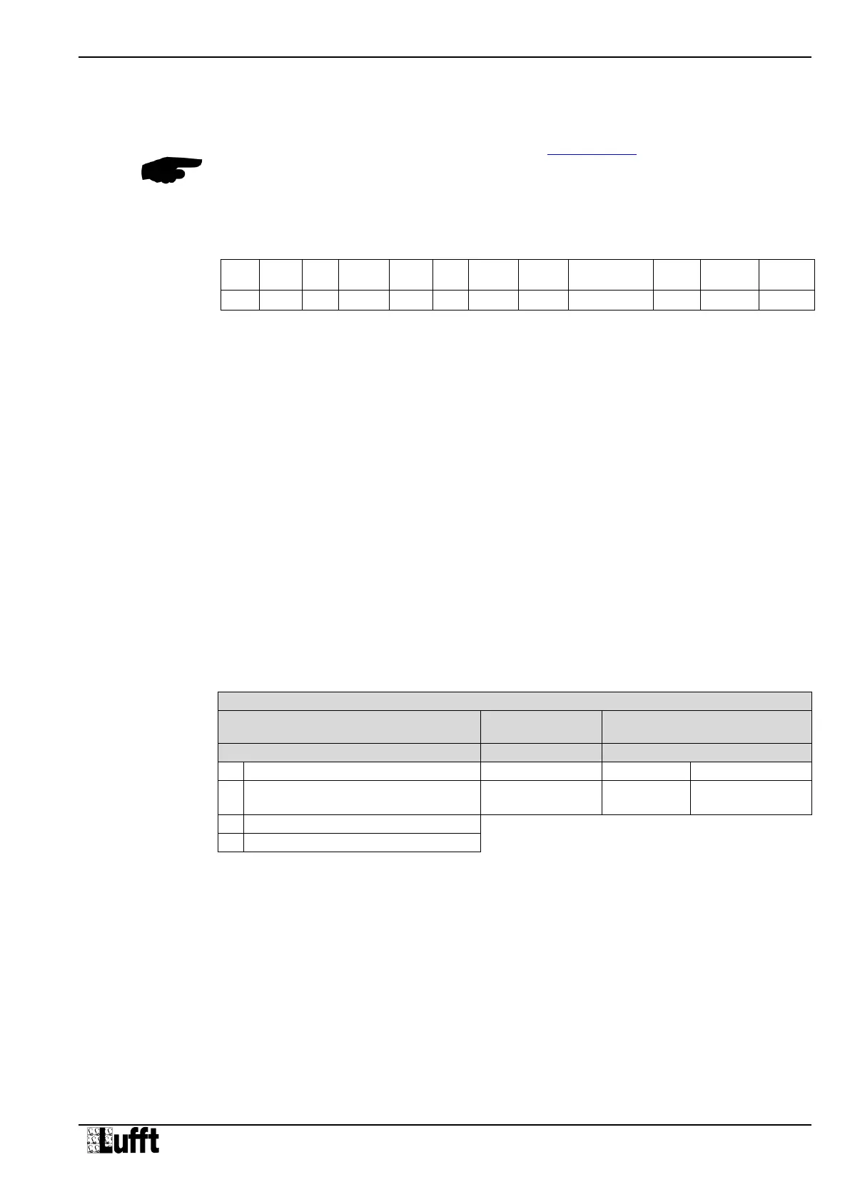
19.3.1 Framing
The data frame is constructed as follows:
SOH Control character for the start of a frame (01h); 1 byte
<ver> Header version number, e.g.: V 1.0 <ver> = 10h = 16d; 1 byte
<to> Receiver address; 2 bytes
<from> Sender address; 2 bytes
<len> Number of data bytes between STX and ETX; 1 byte
STX Control character for the start of payload transmission (02h); 1 byte
<cmd> Command; 1 byte
<verc> Version number of the command; 1 byte
<payload> Data bytes; 0 – 210 bytes
ETX Control character for the end of payload transmission (03h); 1 byte
<cs> Check sum, 16 bit CRC; 2 bytes
EOT Control character for the end of the frame (04h); 1 byte
Control characters: SOH (01h), STX (02h), ETX (03h), EOT (04h).
19.3.2 Addressing with Class and Device ID
Addressing takes place by way of a 16 bit address. This breaks down into a Class ID and a
Device ID.
Address (2 bytes = 16 bit)
Bits 15 – 12 (upper 4 bits)
Bits 11 – 8
(middle 4 bits)
Bits 7 – 0 (lower 8 bits)
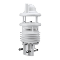
Smart Weather Sensor
(WS200-UMB – WS600-UMB)
Master or control devices
ID = 0 is provided as broadcast for classes and devices. Thus it is possible to transmit a
broadcast on a specific class. However this only makes sense if there is only one device of
this class on the bus; or in the case of a command, e.g. reset.
11 ... (8 + len)
optional