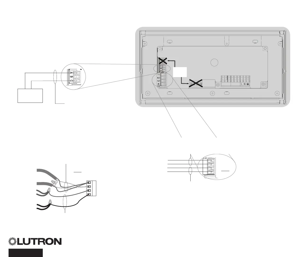
Contact Closure Input Wiring
24 V- 50 mA
For settings, see CCI Setup.
1234
Note: Use appropriate wire
connecting devices as
specified by local codes.
Example:
Third-party contact
closure to enable /
disable timeclock
1: COM
2: 24 V-*
3: MUX
4: MUX
Control Wiring
24 V- 100 mA
Overview of IEC PELV/NEC® Class 2 Wiring
18 AWG (1.0 mm
2
)
each terminal
A: CCI SIG
B: 24 V-
C: CCI COM
To other
QS devices
Data (terminals 3 and 4):
Twisted, shielded pair 22 AWG (0.5 mm
2
) each terminal
Common and power (terminals 1 and 2):
Two 18 AWG (1.0 mm
2
) each terminal (for link <500 ft/153 m)
Two 12 AWG (4.0 mm
2
) each terminal (for link 500–2000 ft/153–610 m)
* Do not connect terminal 2
between a QS Timeclock
and any other power supply.
QS Timeclock Installation and Operation Guide 5
IEC PELV/NEC® Class 2 control wiring
(2) 18 AWG (1.0 mm
2
)
1: Common
2: 24 V-
Wiring Detail
For links 500–2000 ft (153–610 m)
4
3
2
1
Data link: (1) twisted, shielded pair
22 AWG (0.5 mm
2
)
3: MUX
4: MUX
(2) 12 AWG
(4.0 mm
2
)
(2) 12 AWG
(4.0 mm
2
)
NOT
USED

 Loading...