EasyManuals Logo
Home>Lutron Electronics>Control Unit>QS Timeclock

Lutron Electronics QS Timeclock User Manual

Lutron Electronics QS Timeclock
192 pages
To Next Page IconTo Next Page
To Previous Page IconTo Previous Page
Page #51 background imageLoading...
Page #51 background image
Guía de Instalación y Funcionamiento del reloj temporizador QS 3
®
D1 D1 D2 D2
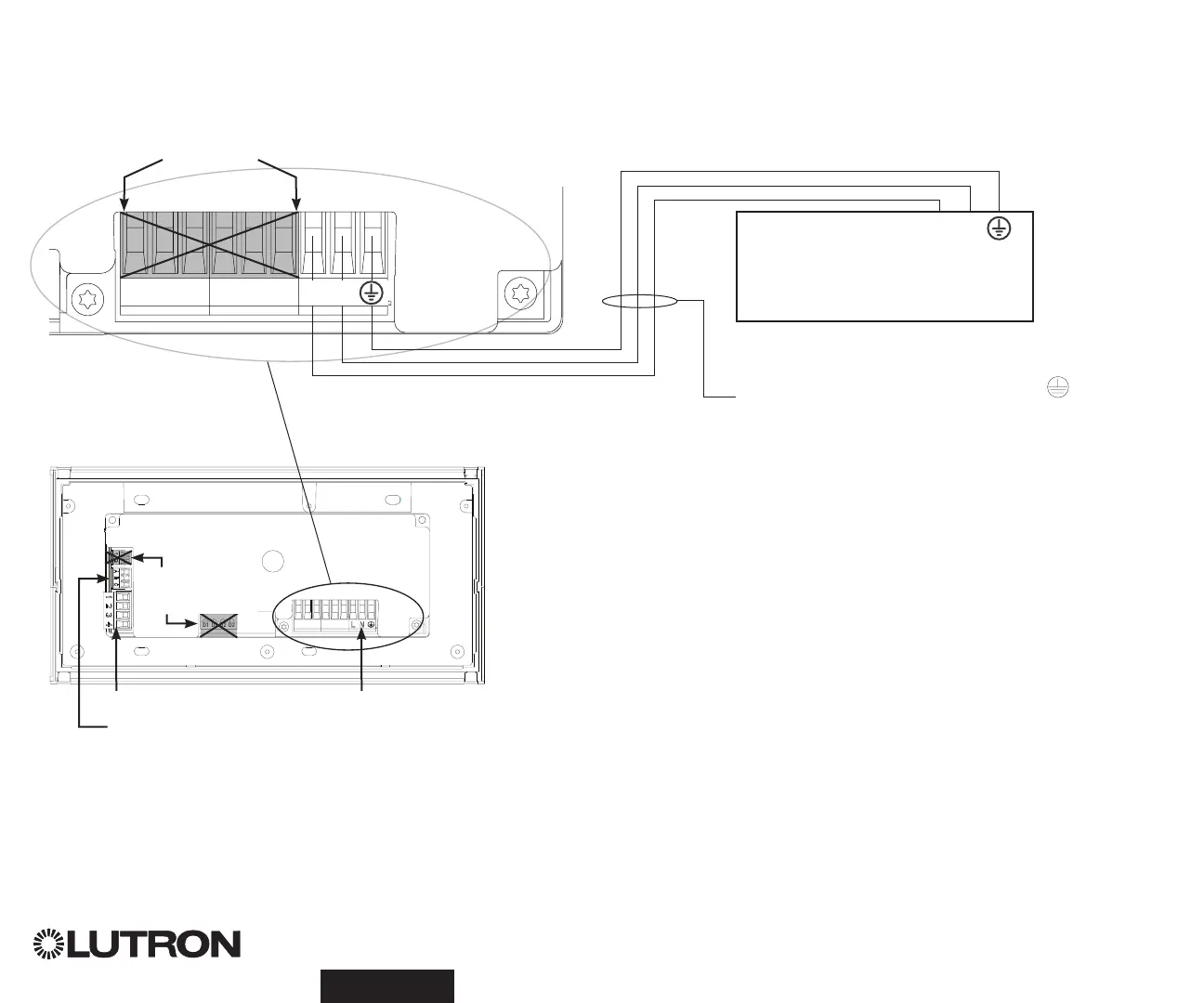
• Lleve el cableado de alimentación desde el panel de distribución hasta el reloj temporizador QS.
• Cada terminal de voltaje de línea puede admitir un cable de 4,0 mm² (12 AWG).
Cableado de voltaje de línea
D1 D1 D2 D2
NO
UTILIZADO
Parte posterior
del Reloj
temporizador QS
1234
12
ABC
123456LN
El voltaje de línea (Línea / Vivo) se
indica con la letra "L".
100–240 V~ sólo
Panel de distribución
1234
12
ABC
123456LN
Terminaciones
Enlace de comunicación QS
Entrada de cierre de contacto y 24 V- energía
NO
UTILIZADO
Entrada de energía
L: Línea / Vivo
N: Neutro
: Tierra

Table of Contents

Other manuals for Lutron Electronics QS Timeclock

Questions and Answers:

Question and Answer IconNeed help?

Do you have a question about the Lutron Electronics QS Timeclock and is the answer not in the manual?

Lutron Electronics QS Timeclock Specifications

General IconGeneral
BrandLutron Electronics
ModelQS Timeclock
CategoryControl Unit
LanguageEnglish

Related product manuals