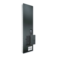
Installation Guide for Switching Panels 15
Ratings (continued)
GRAFIK Systems
TM (XP)
3Ø 4W or
1Ø 3W
Main Lug Accepts:
#4 AWG to 250
KCMIL (MCM)
(25-120 mm
2
)
120 V Panels
with Branch Circuit Breakers
XP
Model
Switch
Legs
Feed
Type
Max
Feed
XP4
XP8
XP12
XP16
XP20
XP24
XP28
XP32
XP36
XP40
XP42
4
8
12
16
20
24
28
32
36
40
42
200 A
225 A
Use the charts below to determine feed and load wiring sizes for GRAFIK Systems panels. Note that load circuit
wiring sizes are shown bottom right.
277 V Panels
with Branch Circuit Breakers
XP
Model
Switch
Legs
Feed
Type
Max
Feed
XP4
XP8
XP12
XP16
XP20
XP24
XP28
XP32
XP36
XP40
XP42
4
8
12
16
20
24
28
32
36
40
42
Load Circuit Wiring
Terminal blocks accept one #14-#10 AWG
(2.5-4.0 mm
2
) wire. Preferred entry is from the
top of the panel.
1Ø 2W
#14-#10 AWG
(2.5-4.0
mm
2
)
Feed-Through (FT) and Rough-In (RI)
Panels (120 V , 277 V , 120/277 V )
FT RI
Model Model
Switch
Legs
Feed
Type
Max
Feed
XP4 XINT4
XP8 XINT8
XP12 XINT12
XP16 XINT16
XP20 XINT20
XP24 XINT24
XP28 XINT28
XP32 XINT32
XP36 XINT36
XP40 XINT40
XP44 XINT44
XP48 XINT48
20 A
3Ø 4W or 1Ø 3W
Main Lug Accepts:
#4 AWG to 250
KCMIL (MCM)
(25-120 mm
2
)
Main Lug Accepts:
#4 AWG to 350
KCMIL (MCM)
(25-185 mm
2
)
250 A
300 A
4
8
12
16
20
24
28
32
36
40
44
48
220-240 V and 230 V Panels
with Branch Circuit Breakers
XPS
Model
Switch
Legs
Feed
Type
Max
Feed
XPS8
XPS12
XPS16
XPS20
XPS24
8
12
16
20
24
3Ø 4W
Isolation Switch
Accepts:
#14-#2 AWG
(2.0-35 mm
2
)
125 A
 Loading...