P 8/ 18
Repair
[4] DISASSEMBLY/ASSEMBLY
[4]-5. Trimmer head ass’y (cont.)
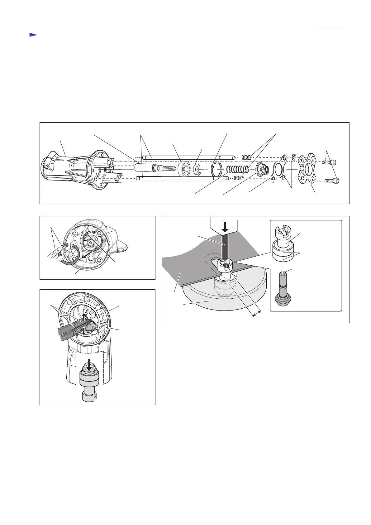
(14) Pipe holder section is now disassembled as drawn in Fig. 26.
(15) Remove Retaining ring R-22 from the inside of Joint with 1R005. (Fig. 27)
(16) Insert the tips of 1R003 in the space between Spiral bevel gear 9 and the round projection in Joint, open the tips to
remove Spiral bevel gear 9 from Joint. (Fig. 28)
(17) Hook Cam A with 13mm width groove of 1R139 and put them on 1R217 so that Cam A comes to the hole. Then, press
down the shaft end of Spiral bevel gear 9 with 1R280. (Fig. 29)
Fig. 26
Fig. 28
Pipe holder
Holder plate
Shaft end of
Spiral bevel
gear 9
Spindle complete Rod 5 (2 pcs.)
Ball bearing
609ZZ
Retaining ring R-22 Compression spring 6 (2 pcs.)
Retaining
ring S-9
Compression spring 9
Round
projection
of Joint
Spiral bevel
gear 9
Cam B
Cam A
Ball bearing
608ZZ (2 pcs.)
Slide plate
Stop ring E-4
(2 pcs.)
M4x16 Hex socket
head bolt (2 pcs.)
Fig. 27 Fig. 29
1R003
1R005
Joint
1R280
Retaining
ring R-22
1R217
13mm
1R139
 Loading...