P 9/ 18
Repair
[4] DISASSEMBLY/ASSEMBLY
[4]-5. Trimmer head ass’y (cont.)
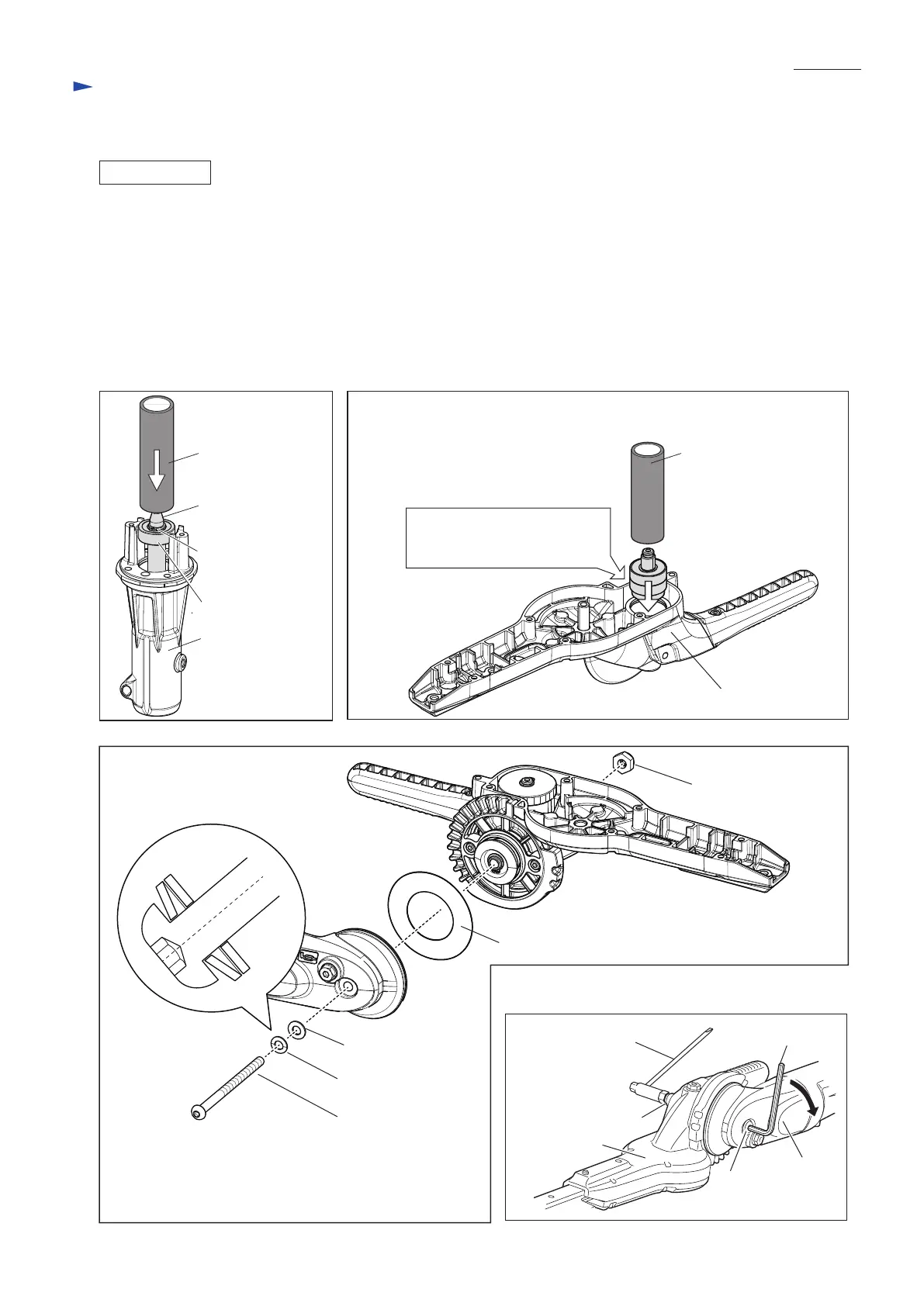
Assemble by reversing the disassembly procedure. Be careful to the following points.
• Press-fit Spindle complete into Pipe holder with 1R029. (Fig. 30)
• Press-fit the module of Spiral bevel gear 12 and two Ball bearings 6000ZZ into Gear housing with 1R030. (Fig. 31)
• Attach the convex portion of Coned disc spring 6 to the bolt head of M6x85 Hex socket button head bolt, then pile Flat
washer 6 on Coned disc spring 6, and last, fasten Joint to Gear housing complete with M6-10 Hex lock nut and M6x85
Hex socket button head bolt. (Fig. 32)
• After adjusting the tightening torque of M6x85 Hex socket button head bolt so that Joint and Gear housing can be set to
the desired angle without any backlash, secure them firmly by tightening M6-10 Hex lock nut with Box driver 10-16 and
Wrench 4 supplied as standard equipment. (Fig. 33)
Fig. 30
Pipe holder
1R029
Fig. 32
Fig. 31
ASSEMBLING
1R030
Gear housing
Spindle complete
Module of
Spiral bevel gear 12
and two Ball bearings 6000ZZ
Retaining ring S-9
Ball bearing 609ZZ
M6-10 Hex lock nut
Gear housing
section
Coned disc spring 6
Joint section
Flat washer 6
Flat washer 36
M6x85 Hex socket button head bolt
Fig. 33
Wrench 4
Joint
M6-10 Hex lock nut
Box driver 10-16
Gear housing
complete
M6x85 Hex socket
button head bolt

 Loading...