Installation and Commissioning
46
Carefully read these Operating Instructions before starting any work!
This is especially valid for the chapter on General Safety Instructions
and the safety instructions in each of the chapters.
6.4.2 Checking crankshaft axial clearance
NOTE
The engines' crankshaft axial clearance specified in the design must not be reduced under any circum
stances as a result of mounting clutches or other attachments.
For this reason:
S It is essential to determine the crankshaft axial clearance using a dial gauge held on a magnetic stand
before and after flange-mounting any attachments.
S Remove V-belt protection.
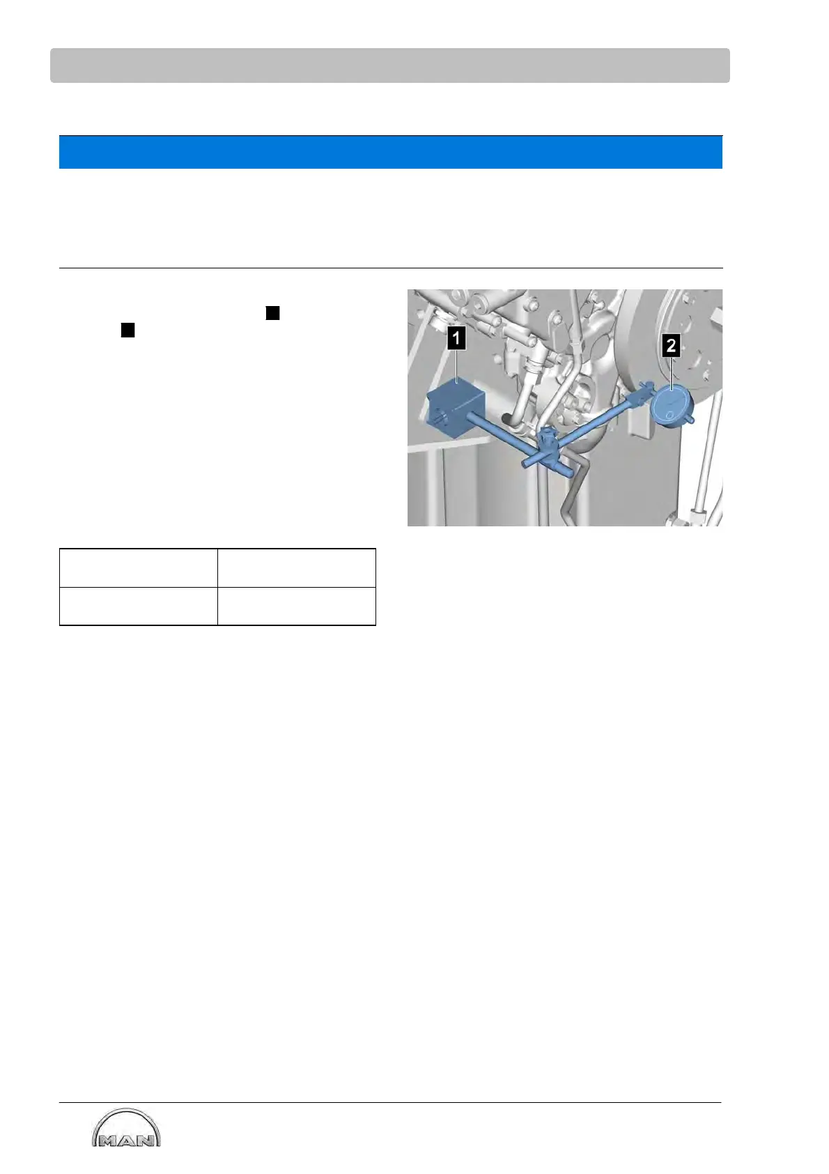
S Position the dial gauge holder
1
with dial
gauge
2
on the engine mounting so that the
dial gauge tracer pin is resting on the vibration
damper with a preload.
S Push the crankshaft towards the flywheel hou
sing in axial direction until the stop is reached.
S Zero the dial gauge.
S Pull the crankshaft away from the flywheel hou
sing in axial direction until the stop is reached
S Check the reading on the dial gauge.
If the results of both measurements do not match,
or if the crankshaft springs back after being mo
ved, check the mounting.
Engines Crankshaft axial clea
rance
E3268LE202 /
E3262 LE202
0.20-0.40 mm
 Loading...

