Manitowoc Published 07-23-15, Control # 078-03 4-51
31000 LUFFING JIB OPERATOR MANUAL SET-UP AND INSTALLATION
53
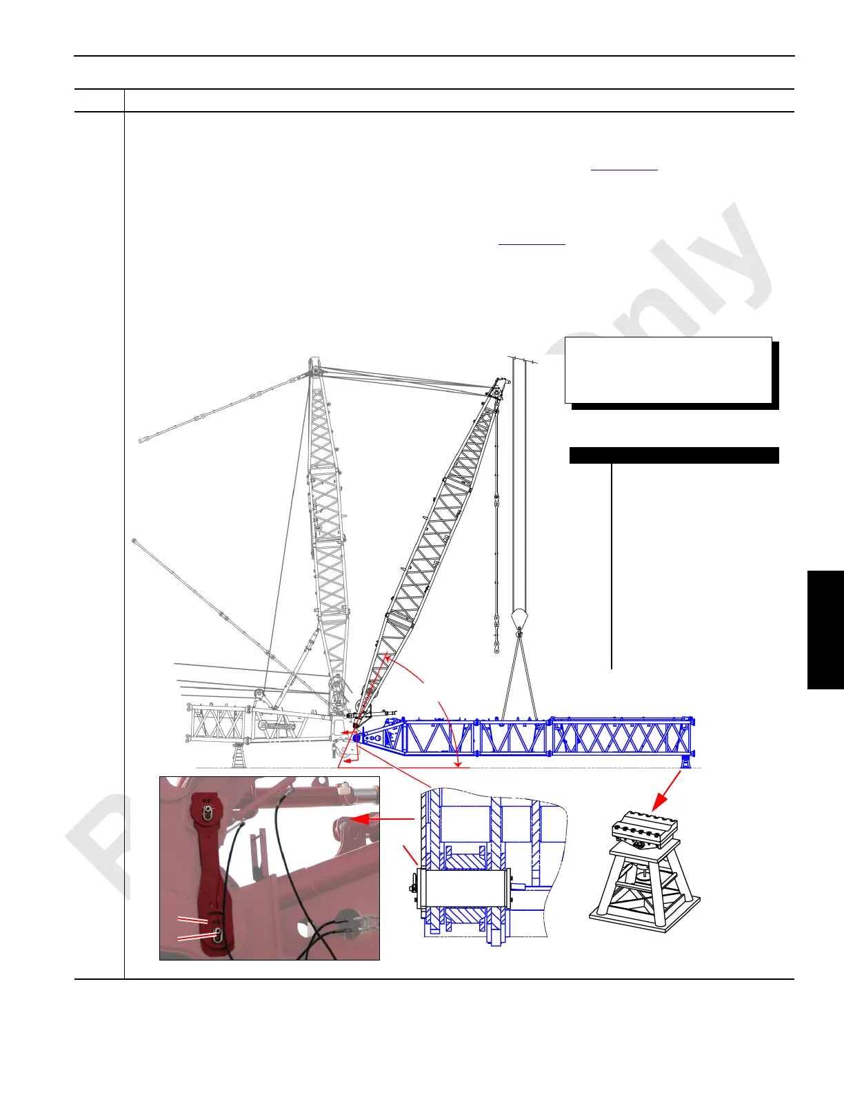
Information below from drawing A19443, Sheet 24:
Attach the #91 luffing jib (B) to the #90 boom top (D):
• Ensure that the cylinders on the jib stop assembly (E) are fully extended (see Figure 4-50
).
• Use an assist crane (A) to raise the jib strut a maximum of 67° above horizontal so that the assist crane (A) wire
ropes clear the jib strut (C) in order to attach the #91 luffing jib (B). The angle shall not exceed 67° or a loss of jib
strut stability may occur.
• Finish the installation of the luffing jib hinge pins (F) started in Figure 4-12
by adding end plates (G) and a swivel
hook (M).
• Use the boom stand (H) to support the #91 luffing jib (B) for the addition of more inserts.
Information below from drawing A19443, Sheet 25:
• Connect the extend (I) and retract (J) hydraulic lines to the hard piping fittings (L) on the jib butt assembly (K).
Step Action
FIGURE 4-53
A
Item Description
A Assist crane.
B #91 luffing jib.
C Jib strut.
D #90 boom top.
E Jib stop assembly.
F Luffing jib hinge pin.
G End plate.
H Boom stand.
I Extend hydraulic line.
J Retract hydraulic line.
K Jib butt assembly.
L Hard pipe fittings.
M Swivel hook.
C
B
D
E
67°
F
H
G
M
Damage will occur if the cylinders on
the jib stop assembly (E) are not fully
extended prior to attaching the #91
luffing jib.

 Loading...


