Do you have a question about the Manitowoc CVD0675 and is the answer not in the manual?
| Model | CVD0675 |
|---|---|
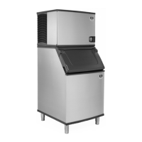
| Type | Undercounter Ice Maker |
| Ice Type | Cube Ice |
| Weight | 240 lbs |
| Daily Ice Production | 675 lbs |
| Condenser Type | Air-Cooled |
| Refrigerant | R-404A |
| Voltage | 208-230V |
| Ice Production | 675 lbs per day |
| Dimensions (H x W x D) | 38.5" x 24" x 28" |
| Production Capacity | 675 lbs per day |
| Power Supply | 208-230V, 60Hz, 1Ph |
Alerts to potential personal injury situations. Read statement before proceeding.
Alerts to situations where equipment could be damaged. Read statement before proceeding.
Provides helpful information to assist with procedures.
Emphasizes proper installation, care, and maintenance for optimal performance.
States that routine adjustments and maintenance are not covered by warranty.
Warns against operating equipment that has been misused or modified.
Notes that ice machine sequences of operation may differ by model.
Warranty coverage begins the day the ice machine is installed.
Advises to mail the registration card to validate the installation date.
Details the warranty periods for ice machine parts.
Details the warranty periods for labor required for repairs.
Lists items and conditions not included in the warranty coverage.
Criteria for selecting the ice machine's location.
Specifies clearance requirements for the ice machine head section.
Criteria for selecting the CVD® Condensing Unit's location.
Specifies clearance requirements for the condensing unit.
Guidelines for installing potable water inlet lines.
Guidelines for installing drain lines to prevent backflow.
General electrical requirements for ice machines and condensing units.
Verification of compressor rotation for 3-phase CVD2075 units.
Table detailing voltage, phase, cycle, breaker, and amps for head sections.
Table detailing electrical specs for CVD condensing units.
Specifications for maximum rise and drop distances.
Requirements for suction line oil traps based on rise.
Procedure for connecting the line set to the ice machine head section.
Specifies insulation thickness for suction and liquid lines.
Ensures proper operation by performing checks after installation or service.
Procedure for checking and verifying the water level.
Procedure for checking and adjusting ice thickness probe.
Detailed steps for performing a cleaning cycle.
Detailed steps for performing a sanitizing cycle.
Diagram and labels for the ice machine head section.
Diagrams and labels for various CVD condensing units.
Diagram and labels specific to the Q1400C model.
Details the ice making sequence for these models.
Details the ice making sequence for the Q1400C model.
Features and diagnostics of the control board.
Explanation of safety limit functions and their purpose.
Function, specifications, and procedure to check the bin switch.
Explanation of the electronic sensing circuit for ice thickness.
Procedure for checking and adjusting the ice thickness probe.
Troubleshooting steps when the machine does not cycle to harvest.
Description of the water level setting during the freeze cycle.
Safety feature limiting water inlet valve on-time.
General diagnostic steps for a head section not running.
Procedure for checking compressor winding resistance.
Diagnosing issues related to locked rotor condition.
Diagnosing issues related to high amperage draw.
Electrical diagrams for various ice machine head sections.
Electrical diagrams for condensing units (1-phase and 3-phase).
Description of the refrigeration cycle during freezing.
Description of the refrigeration cycle during harvest.
Lists symptoms indicating an undercharged refrigerant system.
Lists symptoms indicating an overcharged refrigerant system.
Checklist to diagnose issues preventing harvest.
Checklist for installation and visual inspection of the machine.
Introduction to built-in safety controls protecting the machine.
Details Safety Limit #1 related to freeze cycle duration.
Details Safety Limit #2 related to harvest cycle duration.
Procedures to determine which safety limit stopped the machine.
Instructions on how to use the refrigeration component diagnostic charts.
Diagnostic charts for single expansion valves.
Diagnostic charts for dual expansion valves.
Function and operation of the headmaster control valve.
Steps to diagnose units during the freeze cycle.
Steps to diagnose units during the harvest cycle.
Detailed procedures for refrigerant recovery and evacuation.
Steps to assess the level of system contamination.
Chart detailing required cleanup procedures based on symptoms.
Steps for replacing pressure controls without refrigerant removal.
Details and replacement part numbers for liquid line filter-driers.
Details and replacement part numbers for suction line filters.
Table of refrigerant charges by model and line set length.
Definition of refrigerant recovery process.
Definition of refrigerant recycling process.
Definition of refrigerant reclamation process.