OPERATING CONTROLS AND PROCEDURES RT9130E-2 OPERATOR MANUAL
3-42 Published 3-1-2018, Control # 559-03
converter via pump disconnect. Pump No. 4 is mounted on a
drive pad of the engine.
The purpose of these pumps is to convert mechanical
energy into fluid energy for the operation of the crane’s
hydraulic components. The pumps operate any time the
engine is running.
Control Lever Operation
The control lever operation for all crane functions is
standard, i.e. the closer the lever is to neutral (center), the
slower the system responds. The control lever should be
returned to neutral to hold the load. Never feather the hoist
control lever to hold the load.
NOTE: Always operate the control levers with slow, even
pressure.
Preload Check
After the crane has been readied for service, an operational
check of all crane functions (with no load applied) should be
performed. The Preload Check is as follows:
NOTE: Carefully read and become familiar with all crane
operating instructions before attempting a preload
check or operating the crane under load. Operate
engine at or near governed RPM during preload
check of crane functions.
1. Engage the parking brake.
2. Extend and set outriggers, and level the crane.
3. Raise, lower, and swing the boom a minimum of 45°
right and left.
4. Telescope the boom in and out.
5. Raise and lower the cable a few times at various boom
lengths. Ensure there is no kinking.
Using Your Load Chart
NOTE: One of the most important tools of every crane is
the load chart found in the crane operator cab.
The load chart contains a large amount of information, which
must be thoroughly understood by the operator.
The load chart contains outrigger capacity charts for fully
extended and mid-extended outriggers for the main boom
and jib, and fully retracted outrigger beams for main boom
only. In addition, the load chart contains two on-rubber
capacity charts: 360° stationary, and pick and carry over
front.
The capacity charts are divided into structural strength and
stability limits. This is shown by the bold line across the chart.
Capacities above the line are structural strength limits and
capacities below the line are stability limits.
The left column is the load radius, which is the distance from
the center of crane rotation to the load center of gravity. The
top row lists various boom lengths ranging from fully
retracted to fully extended or jib lengths and offsets. The
number at the intersection of the left column and top row is
the total load capacity for that load radius and boom length or
jib lengths offset. The number in parentheses below the total
load capacity is the required boom angle (in degrees) for that
load. When the boom length or lift radius or both are between
values listed, the smallest load shown at either the next
larger radius or next longer or shorter boom length shall be
used.
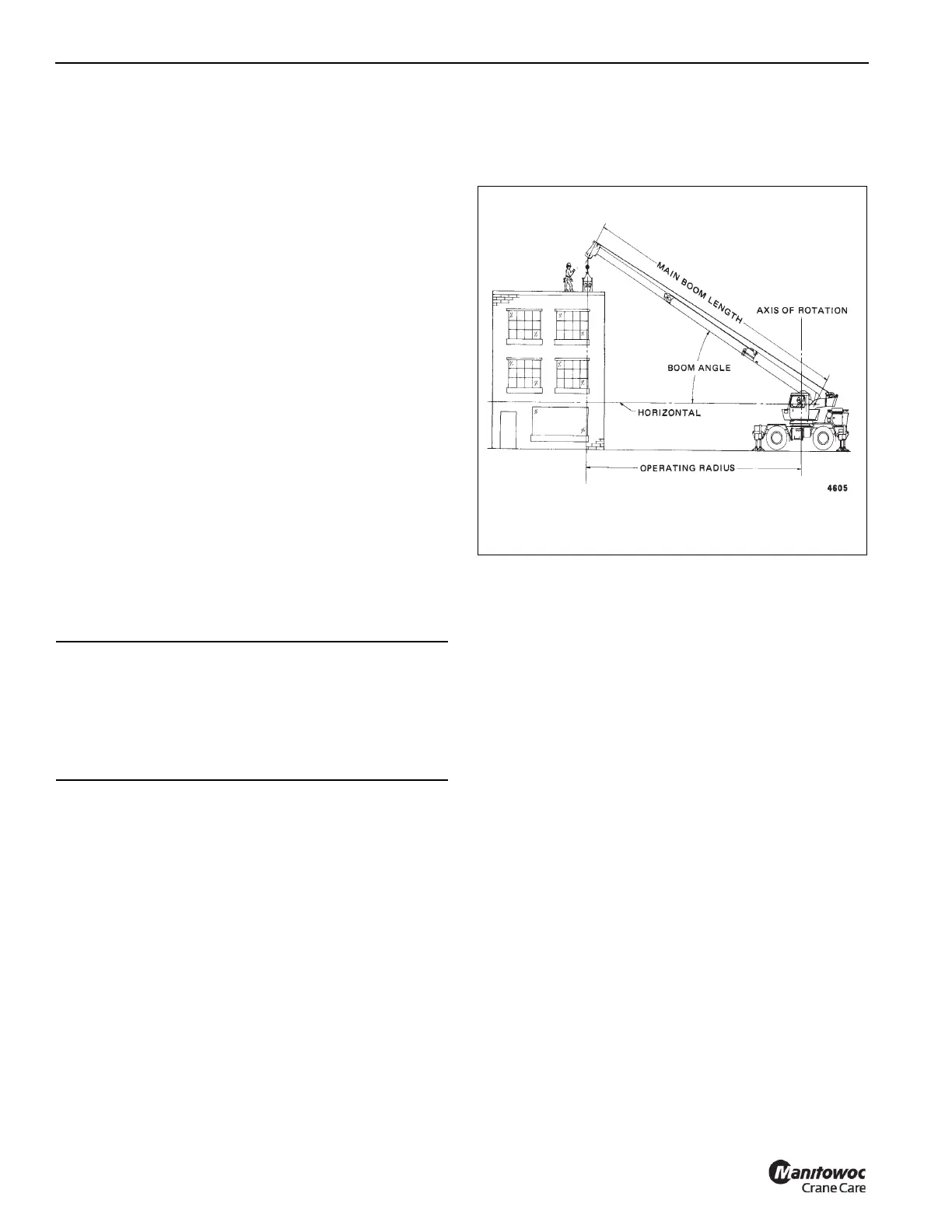
Another important section is the range diagram. The range
diagram shows the operating radius and tip height that can
be achieved at a given boom length and angle. If the
operator knows the radius and tip height required for a
specific lift, the angle and boom length can be quickly
determined from the range diagram. Or, if the boom length
and angle are known, the tip height and operating radius can
be quickly determined.
A lifting diagram is included to describe over side, over rear,
and over front lifting areas. The lifting area diagram shows
that the locations of the outrigger jack cylinders in the fully
extended position are used to mark the boundaries of the
lifting areas.
CAUTION
Avoid Crane Damage!
Do not engage the parking brake while the vehicle is
moving. Damage to the crane can occur.
Disengage the parking brake before driving. Damage to
the crane can occur.

 Loading...


