OPERATING CONTROLS AND PROCEDURES RT9130E-2 OPERATOR MANUAL
3-20 Published 3-1-2018, Control # 559-03
LUFFING JIB RAISE/LOWER SWITCH
(OPTIONAL)
The Luffing Jib Raise/Lower Switch (18) is located on the
right armrest. It is a three position, momentary switch (Lower/
Off/Raise) that energizes a solenoid to actuate the luffing jib
cylinder, it raises or lowers the jib when the Luffing Jib On/Off
switch is On.
LUFFING JIB ON/OFF SWITCH (OPTIONAL)
The Luffing Jib On/Off Switch (19) is a two position switch
located on the right armrest. When in the On position it
energizes the Luffing Jib Raise/Lower Switch to operate the
luffing jib.
TWO-SPEED SWING SWITCH
The Two-Speed Swing Switch (20) is located on the left
armrest. This two-position (fast/slow) switch determines the
swing motor speed. When in the fast position, the swing high
speed solenoid is energized.
ARMREST SWITCH (NOT SHOWN)
The Armrest Switch is a proximity switch located in the left-
hand armrest. The left-hand armrest must be in the down
position before crane functions can be activated.
SEAT SWITCH (NOT SHOWN)
This switch is located in the seat. An operator must be sitting
in the seat before the crane functions can be activated.
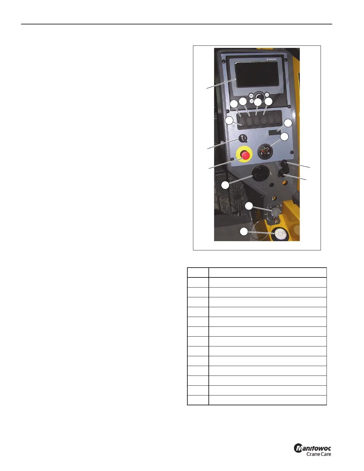
SIDE CONTROL PANEL
Figure 3-11 Item Numbers
Item Description
1 Rated Capacity Limiter (RCL) Display
2 Rated Capacity Limiter (RCL) Bypass Switch
3 Emergency Stop Switch
4 Transmission Oil Temp Gauge
5 AC/Heater Vent
6 Turntable Pin Swing Lock Control
7 12 Volt Receptacle
8 Diagnostic Connector
9 Bubble Level Indicator
10 Boom Not Sync Indicator
11 Hose Reel Brake
12 minimum Wrap Indicator (optional)
13 Cold Weather Indicator (optional)
7649-7
FIGURE 3-11
1
3
2
5
7
4
8
6
9
10
12
11
15
13
14

 Loading...


