OPERATING CONTROLS AND PROCEDURES RT9130E-2 OPERATOR MANUAL
3-14 Published 3-1-2018, Control # 559-03
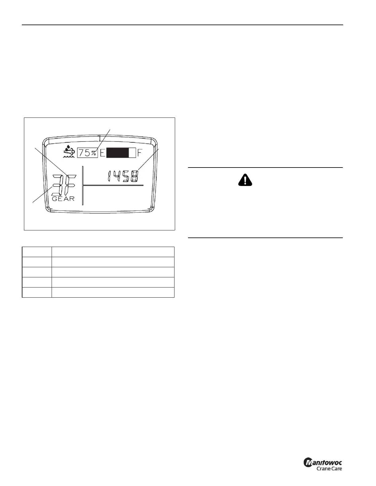
LCD Display
The LCD Display(12, Figure 3-7 and Figure 3-8) is located in
the steering column gauge display. The display shows the
transmission gear being used, fault codes, DEF level and
master software version.
If an active engine fault code is present, the display will show
the code when the Ignition Switch is in the RUN position and
the engine is off. The display will show the master software
version when the Ignition Switch is in the ACC position.
Figure 3-8 Item Numbers
Engine Stop
The Engine Stop Indicator (13, Figure 3-7) is located in the
steering column gauge display. It illuminates red when
energized by a signal from the engine ECM. In addition, a
warning buzzer will also sound.
If this indicator light illuminates note the fault code and shut
off the engine and refer to the Engine Operator Manual.
Engine Warning
The Engine Warning Indicator (14, Figure 3-7) is located in
the steering column gauge display. It illuminates amber when
energized by a signal from the engine ECM.
If this indicator light illuminates note the fault code and refer
to the Engine Operator Manual.
NOTE: This lamp may also illuminate along with the
Exhaust System Cleaning Required lamp or Low
DEF Level lamp (18).
Exhaust System Cleaning (Tier 4 Engines
Only)
The Exhaust System Cleaning Required Indicator (15,
Figure 3-7) is located in the steering column gauge display.
This indicator illuminates amber when the exhaust system is
in need of cleaning.
The indicator will be lit continuously during the early stages
of required cleaning. If this condition continues, the lamp will
begin to flash and a slight engine derate will occur.
If this condition continues further, the Engine Warning light
(14) will illuminate in addition to the Cleaning indicator (15)
and a severe engine derate will occur.
The only way in which either of these conditions can occur is
if cleaning has been inhibited or a manual cleaning was
interrupted. Refer to Exhaust System Cleaning Switch (Tier
4 Engines Only), page 3-10, for more detail on these.
The cleaning process can take place in three different
modes:
Passive: the exhaust is hot enough during normal working
operation to burn off any hydrocarbon (soot) accumulation.
Active: Active cleaning occurs when there is not sufficient
heat in the exhaust to perform the cleaning operation when it
is required. Exhaust temperatures are raised by the system
sufficiently high to enable a cleaning to occur. This is all done
without any operator intervention. When the Cleaning Switch
(9, Figure 3-4) is in the active cleaning (center) position,
active cleaning is enabled. This is recommended.
Manual: Manual or stationary, cleaning is the same as active
cleaning but takes place while the equipment is not being
operated. It offers the equipment operator the option, if
needed, of performing cleaning outside the normal duty
cycle. When the Cleaning Switch (9, Figure 3-4) is
momentarily placed in the manual cleaning position, manual
cleaning is initiated. Often this is preceded by the Cleaning
Switch (9, Figure 3-4) being placed in the inhibit cleaning
position, which can lead to the engine operational
implications discussed above.
Item Description
1 Transmission Gear
2 Forward or Reverse, Transmission
3 Engine Fault Code, Master Software Version
4 DEF Level/Gauge
WARNING
Extreme Heat Hazard!
During the cleaning process the exhaust becomes very
hot. Do not park the vehicle near objects that are
flammable.
Use caution near the exhaust tailpipe as it will also
become very hot.

 Loading...


