OPERATING CONTROLS AND PROCEDURES 5540F/YB5515 OPERATOR’S MANUAL
3-22 Published 10-21-2011, Control # 055-03
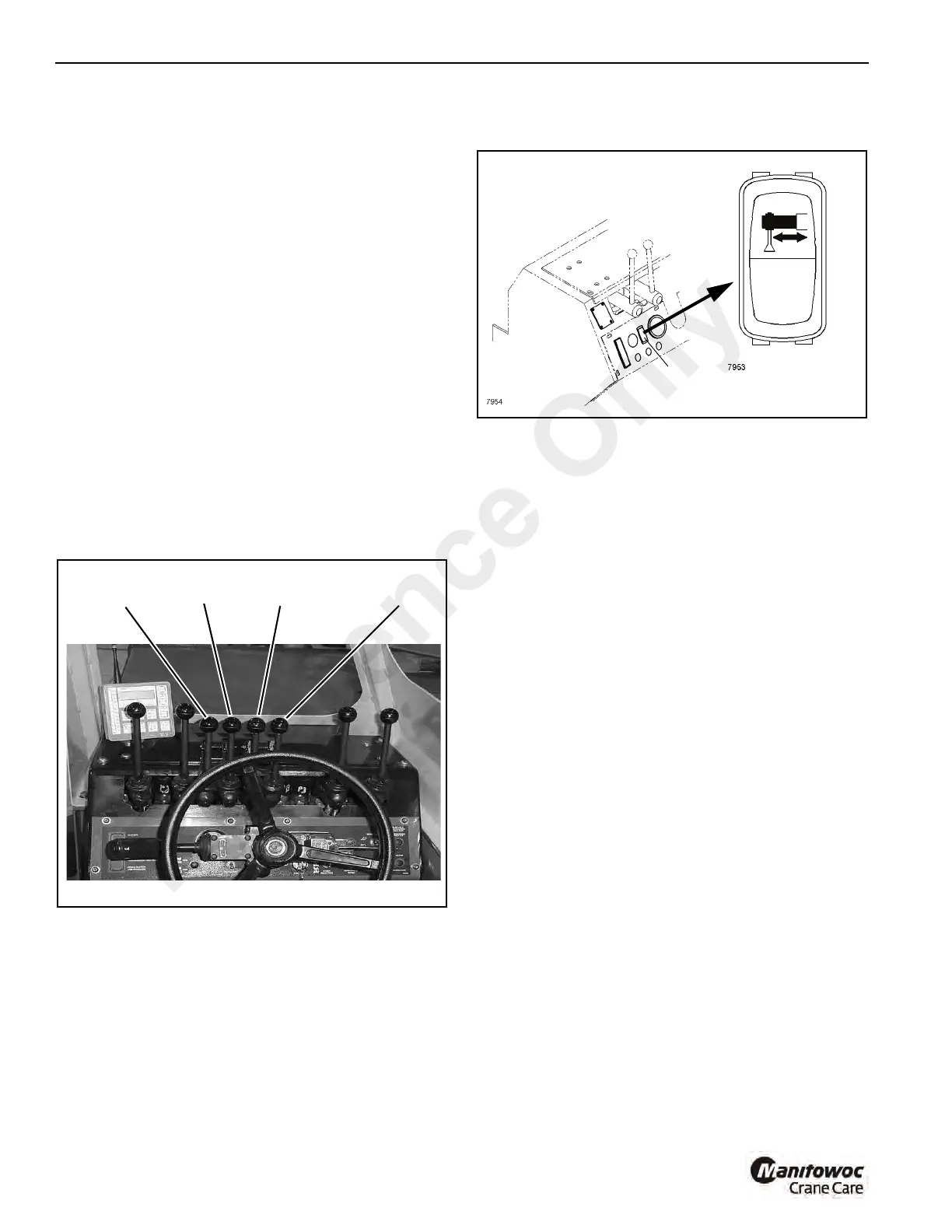
Independent Outriggers
To Raise and Lower the Outriggers
On cranes equipped with independent outrigger controls,
each outrigger is independently controlled (Figure 3-46).
Two or more outriggers may be simultaneously lowered or
raised by simultaneously actuating the controls for each of
the outriggers.
1. Determine which outriggers are to be raised or lowered;
left, right or all.
2. To Lower - (Figure 3-48) Run the engine at idle speed
(accelerator pedal released). Move the control lever
forward to the LOWER position and hold it in position.
Press the accelerator pedal to increase the engine
speed, which will accelerate the outward movement of
the outrigger. Release the accelerator pedal and the
outrigger control lever when the outrigger is extended.
3. To Raise - (Figure 3-48) Pull the control lever back to
the RAISE position and hold it in position. Press the
accelerator pedal to increase the engine speed, which
will accelerate the retracting speed of the outrigger.
Release the accelerator pedal and the control lever
when the outrigger is fully raised.
Outrigger Monitoring System (OMS)
(Optional—Standard in North America)
The Outrigger Monitoring System (OMS) aids the operator
by using an indicator (1, Figure 3-47) on the control panel
that lights when all outriggers are fully deployed. The OMS
uses four proximity sensors, one per outrigger beam, to
identify when an outrigger beam is fully extended.
Set up of the outriggers is the same for cranes equipped with
OMS; refer to “Operating the Outrigger Controls” on
page 20. The OMS indicator only indicates the fully extended
position of the outrigger beam and should not be used to
deploy the beam.
Outriggers fully retracted or outriggers fully extended are the
only outrigger positions documented on the Load Charts.
Each proximity switch senses the presence of it’s respective
outrigger beam until the beam reaches it’s fully extended
position.
Proximity switch outputs are wired in series such that when
all outrigger beams are fully extended, each proximity switch
will no longer sense presence of it’s outrigger beam, the
output contact will then close illuminating the green indicator
on the control panel signaling all outriggers are fully
extended and lifts can be made per “outriggers fully
extended” Load Chart.
Any outrigger beam not fully extended or functional failure of
any proximity switch will cause the indicator to not illuminate,
indicating outrigger beams are not fully extended and lifts
can only be made per the ”outriggers retracted” or “on
rubber” Load Charts.
Outrigger beam position monitor is not interfaced with the
load monitoring system (if equipped), the machine operator
is responsible for selecting the correct load chart.
p1616
Independent Outrigger Controls
FIGURE 3-46
Left Rear Left Front
Right Front
Right Rear
 Loading...


