3.2 Description of LED indicator
Startup in progress
(initialization)
Green light Orange light
3.3 Tally Indicator Light Function Description
3.3.1 The tally indicator light function may be enabled through the control of RS-232
command. The setting method is as follows:
Tally Mode: 8x 01 7E 01 0A 01 0p FF
p = 0: OFF
p = 4: Red light (half-brightness)
p = 5: Red light (full-brightness)
p = 6: Green light (full-brightness)
p = 7: Orange light (full-brightness)
Chapter 4 Instruction for installation
4.1 Preparation before installation
Installation and setup of CV630-IP cameras requires special skills. To install by yourself,
please follow necessary steps, ensure steady and secure mounting of the device, and pay
attention to your safety to avoid any accidents, drops, or damage.
4.1.1 Ensure the safety of the installation environment. Please do not install the device on
unstable ceiling fixtures or in places where the device would be in danger of falling.
4.1.2 Please check whether accessories in the box are complete. Please contact the
Marshall Electronics immediately for any shortages or missing items, and make sure to
keep the accessories in the box if not used.
4.1.3 Please choose a proper place for installation of camera in advance. Please determine
an installation spot according to the following requirements
•
Confirm the position of target objects to be captured.
•
Confirm camera position based on light, and proper distance from light sources.
4.2 Instruction for installation
4.2.1 I would like to install camera on the desk
4.2.1.1 Precautions for installation
◆ Please install camera only on flat desk surfaces
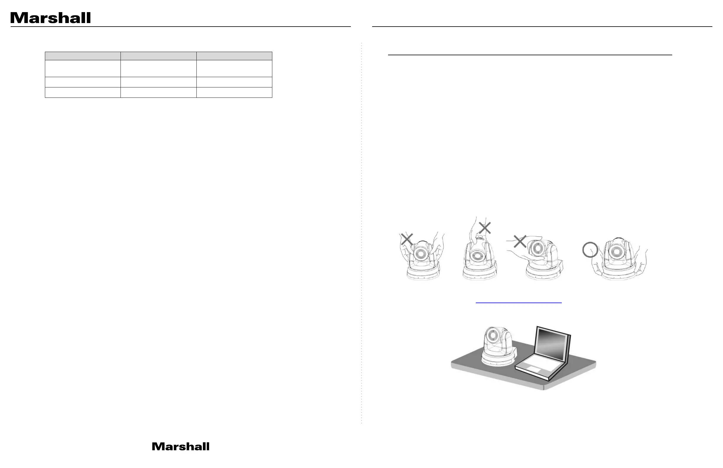
◆ Do not grab or carry the camera by the camera head
◆ Do not rotate the camera head by hand, improper rotation may result in breakage of
PT motors or gears of the camera
4.2.1.2 Installation steps
1. Please adjust DIP switch to desired resolution and framerate prior to installation.
Please refer to Chapter 7 DIP Switch Setting for the relevant descriptions on DIP
switch settings.
2. Place the camera only on flat desk surfaces to ensure integrity of normal vertical
and horizontal axis of operation
4.2.2 I would like to install the camera on the ceiling
4.2.2.1 Prepare for the parts and equipment required before the installation
1. Accessories in the box (metal plates A, B, M3 screw silver x 8, black x 2)
2. Set screws for locking camera on ceiling mounted hanger x 4
3. Drill, screwdriver, and ladder
CV630-IP Manual
www.marshall-usa.com7 8
 Loading...