21 22
4.10 Measuring Inrush Current
WARNING
Beware of Electrocution.
Ensure that the test leads are disconnected
from the meter before making current clamp
measurements.
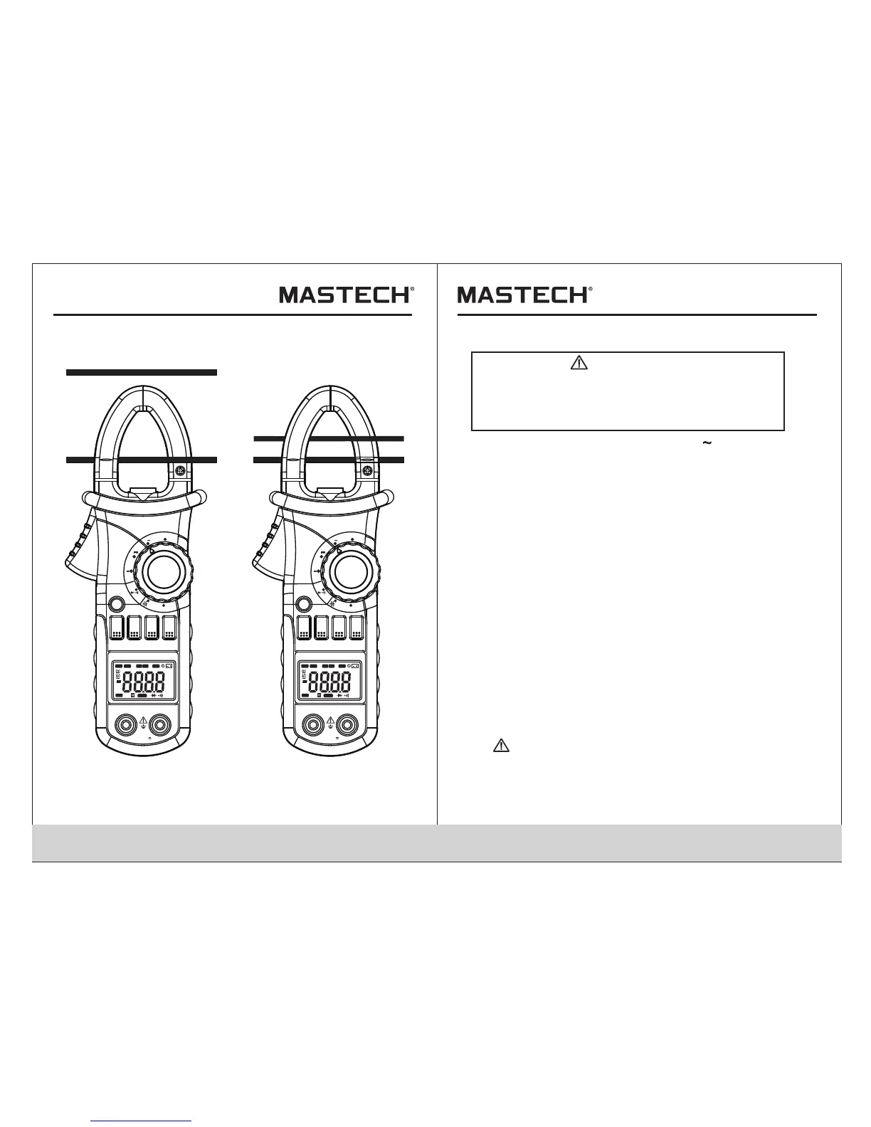
4.10.1 Set the rotary selector to the A range position.
4.10.2 Press the trigger to open jaw. Fully enclose
only one conductor.
4.10.3 Press the “SEL” to enter the INRUSH current
measurement mode. Then LCD displays
“- - - -” until the motor starting up and being
detected. The detection will be done only one
time and the output reading will be hold.
4.10.4 Take the reading on the LCD.
Note:
1) Do not put more than one cable into
the jaw during test, otherwise incorrect
test value might be obtained.
2) For optimum results, center the conductor in the jaw.
3) At the manual range mode, when only ‘O L’ is shown
on the LCD, it means the measurement has
exceeded the range. A higher range should
be selected.
4) Under the manual range mode, when the scale of
the value to be measured is unknown beforehand,
set the range to the highest.
5) “ ” means the maximum input current is
600A rms AC.
V
OFF
Ω
OFF
A
MAX
MIN
RAN
HOLD
B.L
Hz/%
SEL
INRUSH
DIGITALCLAMP
A
V
OFF
Ω
OFF
A
MAX
MIN
RAN
HOLD
B.L
Hz/%
SEL
INRUSH
DIGITALCLAMP
A
COM
INPUT
COM
INPUT
CAT.III
MAX600V
600V
CAT.III
MAX600V
600V
Hz
AUTO
MANU
MAX MIN
ZERO
°C°F%
μmVA
nμmF
MkΩ
INRU SH
TRMS
Hz
AUTO
MANU
MAX MIN
ZERO
°C°F%
μmVA
nμmF
MkΩ
INRU SH
TRMS

 Loading...