39 40
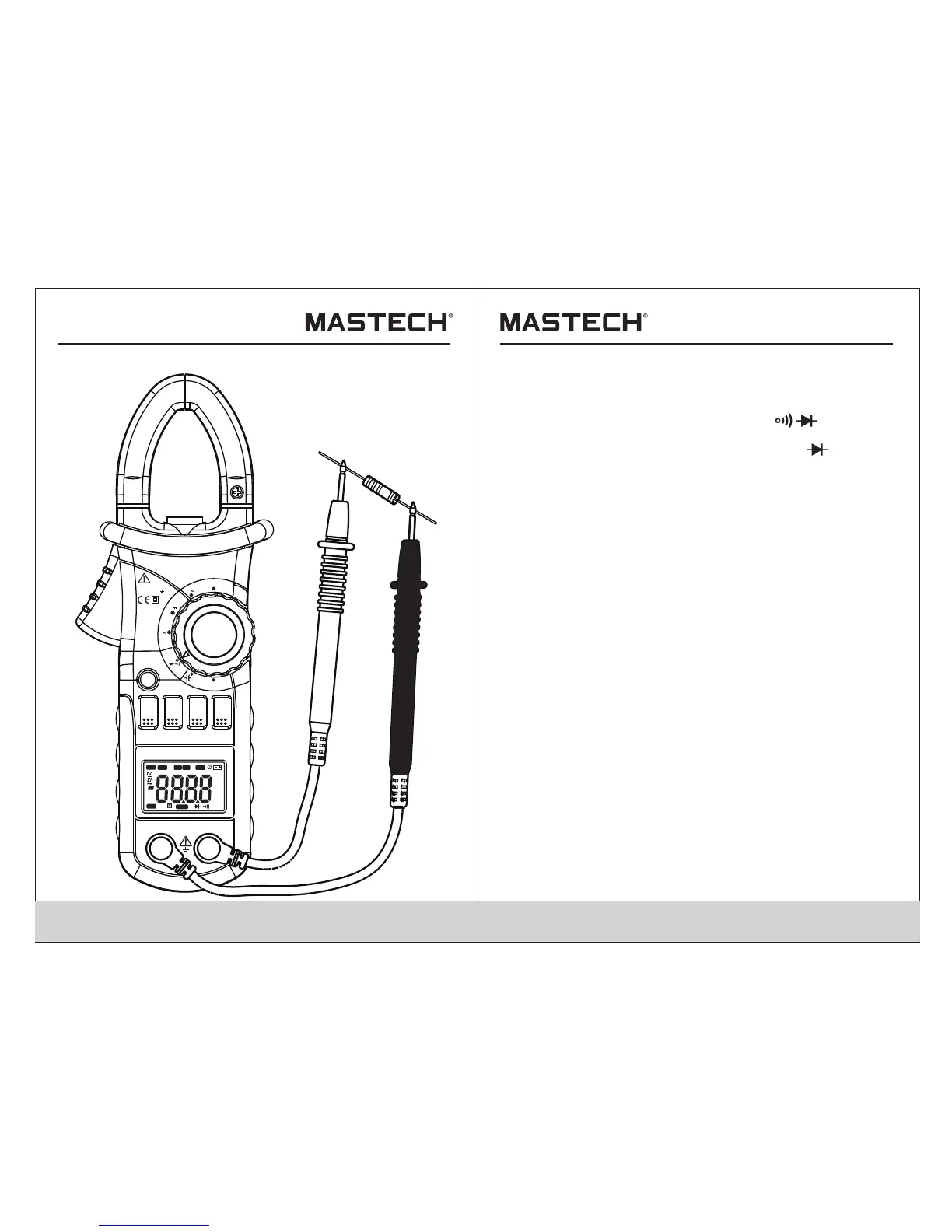
4.17 Testing Diode
4.17.1 Plug the black test lead into the COM jack and
the red test lead into the INPUT jack.
4.17.2 Set the rotary selector to the Ω range
position.
4.17.3 Press the "S E L" button to switch to test.
4.17.4 Connect the red test lead to the anode and the
black test lead to the cathode of the diode for
testing.
4.17.5 Take the reading on the LCD.
Note:
1) The meter will show the approximate forward voltage
drop of the diode.
2) When the test leads have been reversed or open,
'O L' will appear on the LCD.
V
OFF
Ω
OFF
A
A
INRUSH
DIGITALCLAMP
COM
INPUT
MAX600A
CAT III 600V
MAX
MIN
RAN
HOLD
B.L
Hz/%
SEL
Hz
AUTO
MAN U
MAX MIN
ZER O
°C°F%
μmVA
nμmF
MkΩ
INR USH
TRM S

 Loading...