9
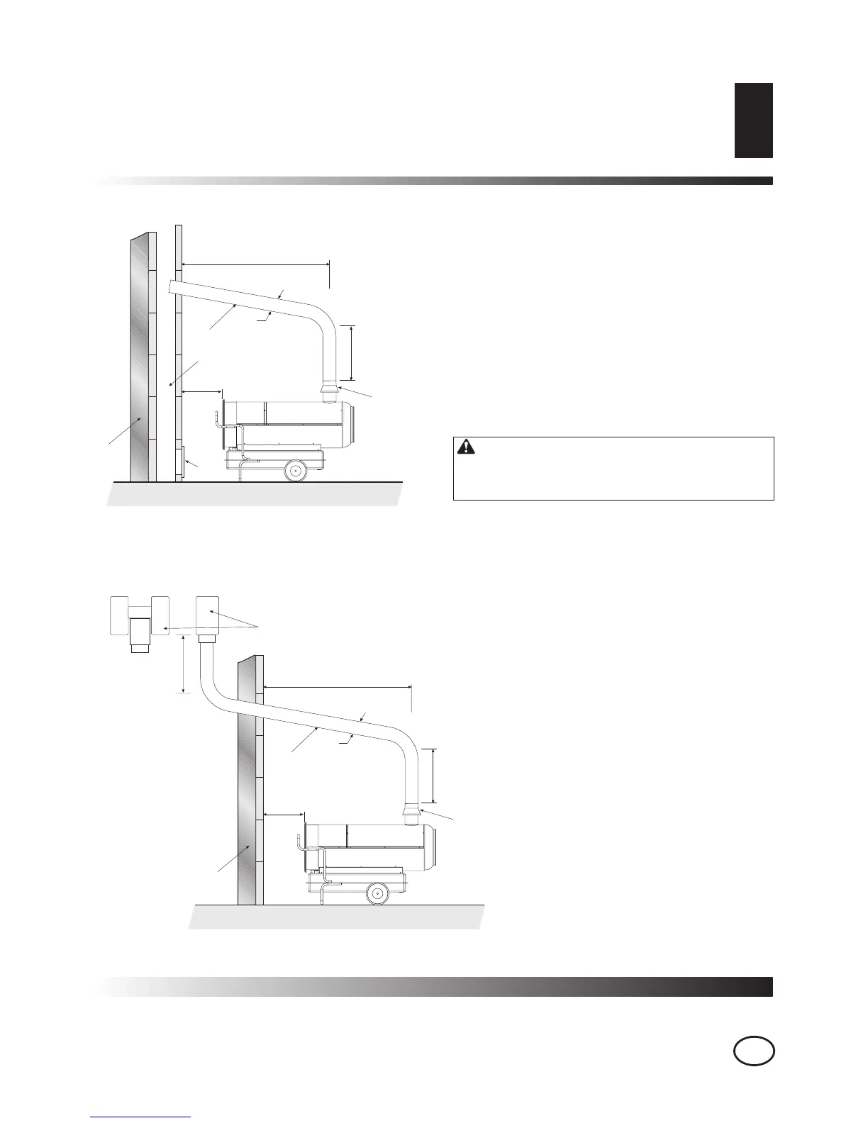
FLUE PIPE POSITIONING DIAGRAM
FLUE PIPE POSITIONING
DIAGRAM
A Minimum 1m
B Minimum 1m
C As short as possible
D Equal to or greater than the diameter of the burner’s fume output
E Minimum 1m
1 Anti-wind device fitted with the heater
2 Horizontal crosspiece with a minimum upwards angle of at least 5°
3 Flue with minimum internal dimensions of 20 x 20 cm
4 Anti-explosion/flue inspection shutter
5 External buffer wall
6 H-shape draw activator
WARNING The diagrams are indicative;
the installation of the flue must meet current
legal norms.
 Loading...