Page 11
mobile part of the window frame using the reference points
indicated on the template.
h) Complete assembly between chain terminal and quick hook
using the Ø4x32 pin provided and insert into central
position (Fig.6).
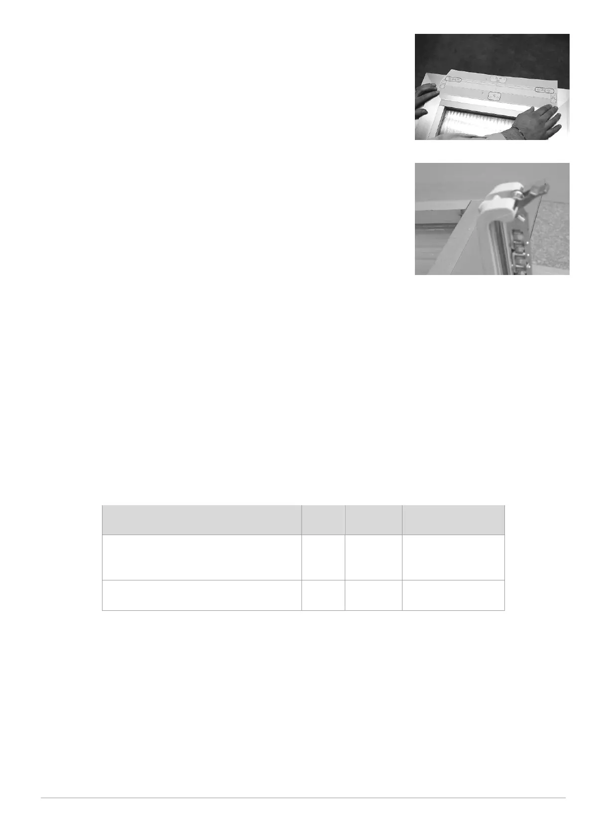
i) Hook the actuator onto the brackets inserting the two
channels at the end of the actuator into the pins provided.
j) Rotate the actuator 90°, bring the chain terminal up to the
hinge and insert the pin into the channel of the latter.
Connect the quick hook onto the rod (Fig. 10).
k) Perform the electrical connections according to the diagram
below or the label on the feeder cable.
l) Check that the output of the chain is perfectly aligned with
the bracket. In the event that this should not be the case,
loosen the fixing screws and reposition the bracket correctly.
Figure 9
m) Perform a complete test of opening and closing of the window frame. After closure,
check that the window frame is completely closed and check pressure against the seals.
n) The stroke-end of the actuator during return is automatic. The appliance exerts traction
of over 280N to guarantee perfect pressure against the seals.
9. Electrical connections
Machines have been equipped with a power connection cable which complies with
safety regulations and protection against radio disturbance.
Before performing the electrical connection consult the table below and check
correspondence between the feeder cable and the tension data on the actuator label.
Voltage
Cable
Number
Colour of wires
110/230V~, 50/60Hz
1 m 3
LIGHT BLUE
BLACK
BROWN
24V═
1 m 2
LIGHT BLUE
BROWN
If feeder cables require extending to the control button for low voltage actuators (24VDC),
cable sections should be selected accordingly.
Conductor sections are indicated in the table on page 8 (Selection of cable section).
For cabling, follow the diagrams below.
 Loading...