8
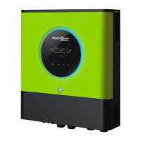
connectors. Then, connect positive pole (+) of connection cable to positive pole (+) of PV input connector.
Connect negative pole (-) of connection cable to negative pole (-) of PV input connector.
Recommended PV module Configuration
PV Module Spec.
(reference)
- 250Wp
- Vmp: 30.7Vdc
- Imp: 8.15A
- Voc: 37.4Vdc
- Isc: 8.63A
- Cells: 60
Communication Connection
Please use supplied communication cable to connect to inverter and PC. Insert bundled CD into a computer and
follow on-screen instruction to install the monitoring software. For the detailed software operation, please
check user manual of software inside of CD.
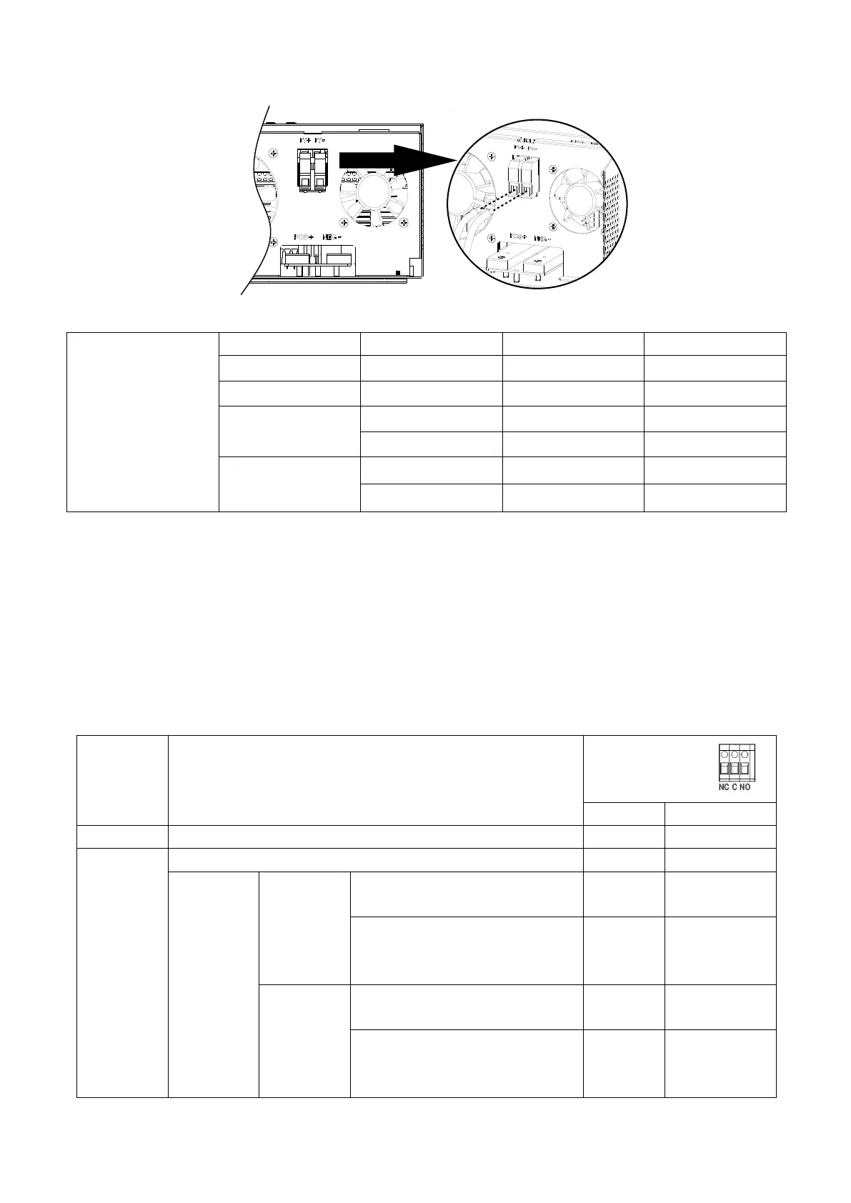
Dry Contact Signal
There is one dry contact (3A/250VAC) available on the rear panel. It could be used to deliver signal to external
device when battery voltage reaches warning level.
Unit is off and no output is powered.
Output is powered from Utility.
Output is
powered
from
Battery or
Solar.
Battery voltage < Low DC warning
voltage
Battery voltage > Setting value in
Program 21 or battery charging
reaches floating stage
Battery voltage < Setting value in
Program 20
Battery voltage > Setting value in
Program 21 or battery charging
reaches floating stage
 Loading...