35
5.12 CHAIN REPLACEMENT
1) Turn off the power and disconnect the cord from the machine.
2) Remove the service cover and side covers as outlined in Section 5.1 & 5,2.
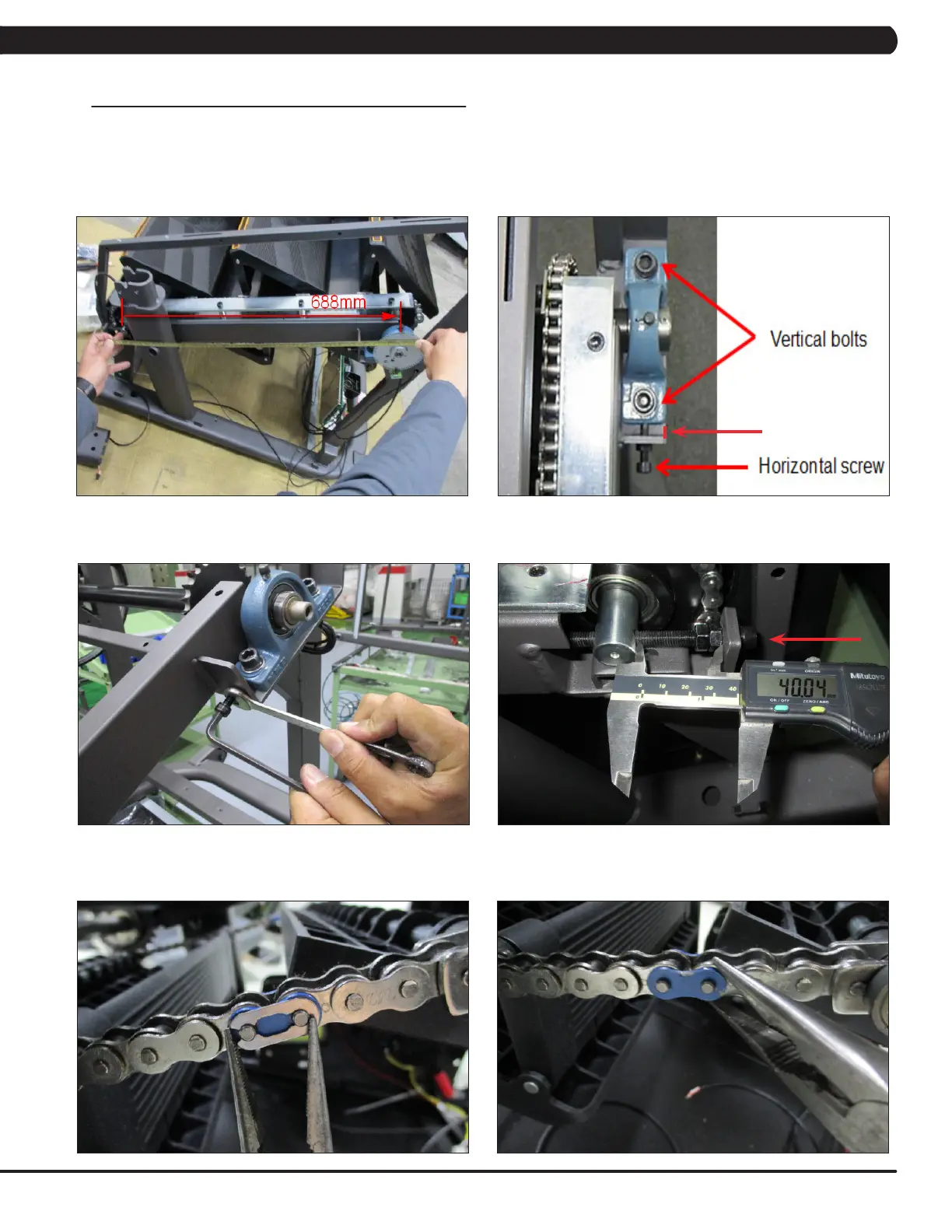
3) Before removing the chain, measure the distance of the chain run from the middle of the front bearing seat to the middle of the rear bearing
seat (Figure A). This distance should be 688 mm.
4) If this length is not 10mm, it needs to be adjusted. Loosen the vertical bolts on the bearing seat, then adjust the length by adjusting the
horizontal screw. Tighten the vertical bolts to tighten the bearing seat in place. The vertical bolts should be tightening to 60 N-m (Figure B & C).
5) If this length is not 40mm, it needs to be adjusted. Loosen the 2 nuts then adjust the length by adjusting the screw. Tighten the 2 nuts to
tighten the chain in place (Figure D).
6) Rotate the chain until a spring clip is in a convenient location and remove it (Figure E). NOTE: This chain link will normally be painted to
make it easier to identify.
7) Remove the join plate on the chain (Figure F).
FIGURE BFIGURE A
FIGURE E
CHAPTER 5: PART REPLACEMENT GUIDE
FIGURE F
FIGURE C FIGURE D
10mm
 Loading...