IM 781-2 Page 27
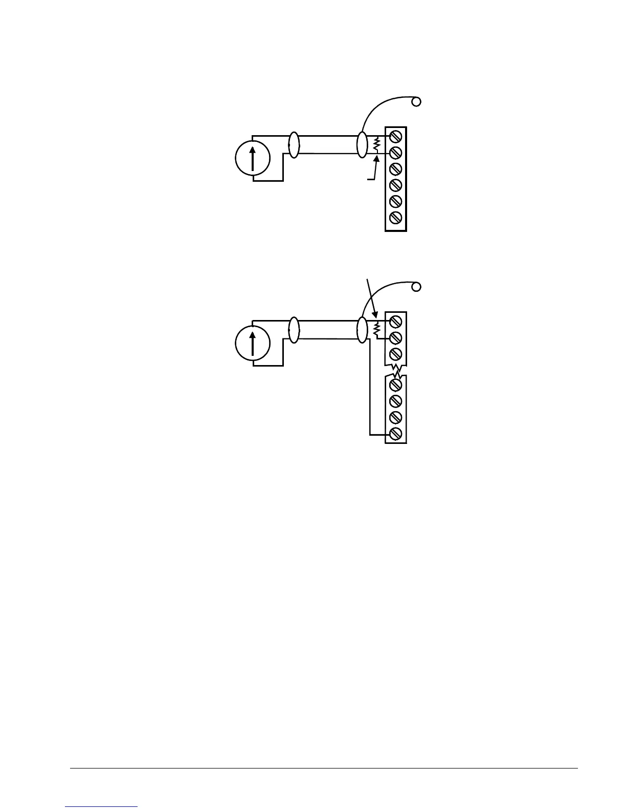
Figure 22. Analog Input 4 to 20 mA Wiring
UI1
G
UI2
Shield
Stud in
enclosur
200' max
Shielded,
Cable
Range: 0-20 mA
4-20 mA
Self-powered
sensor
+
-
i
499 Ohm
(supplied with
UI1
G
UI2
Shield
Stud in
enclosur
200' max
Shielded,
Cable
Range: 0-20 mA
Controller-powered
sensor
+
-
i
499 Ohm
(supplied with
AO3
AO2
AO1
AV+
1. Flow Rate Sensor (UI 7)
A water flow rate sensor is used by the CSM in decoupled chiller sequencing control (primary/secondary systems) to
determine when the system capacity should be decreased by one stage. See Figure 7 through Figure 10 for the location of
the flow rate sensor mounted in the decoupler line. The flow rate sensor can also be mounted in the common supply water
line (after the decoupler line and before the first cooling load branch line). In this case, the CSM calculates the decoupler
line flow by subtracting the primary flow from the measured common supply water line reading.
Note that since flow is only measured in one direction, a uni-directional flow meter is sufficient. If the flow meter is
mounted in the decoupler line it must be sized to measure up to 150% of the evaporator flow rate of the largest chiller. If
the flow meter is mounted in the common supply line it must be sized to measure the total flow capacity of the cooling load
pumps.
When the flow rate from supply to return in the decoupler line is greater than the flow rate of the next chiller to be staged
off by more than the adjustable differential, the system capacity may be reduced by one stage.
2. Chilled Water Loop Differential Pressure Transducer (UI 8)
The chilled water loop differential pressure transducer is used when chilled water loop bypass valve control, sequencing
pump control, or variable speed pump control is required. See Figure 8, Figure 10, and Figure 11. A quality differential
pressure sensor should be selected since water hammer can occur within the loop.
When loop bypass valve control is used, the chilled water loop differential pressure transducer allows the CSM to modulate
a bypass valve as required to maintain an adjustable differential pressure setpoint using a PI (proportional-integral) control
loop.

 Loading...


