IM 781-2 Page 49
!
WARNING
Electric shock hazard.
Can cause personal injury or equipment damage.
Installing current transducers on a chiller or on any energized conductor may cause severe injury or death.
Disconnect and lock out all power sources before installing or servicing current sensing devices. Connections and
service must be performed by trained personnel.
Only use current transducers with 4-20 mA output signals. The remote I/O modules analog inputs have impedance of
20,000 ohms, which are not high enough for accurate readings with 0-5 VDC or 0-10 VDC current transducers.
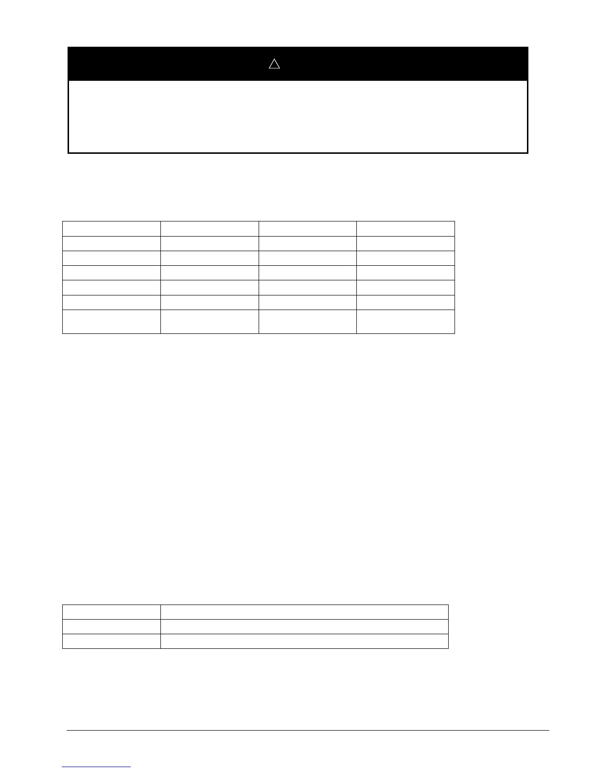
Table 9. Current Transducer Specification
Range 0-300 Amps 0-800 Amps 0-2400 Amps
High Range Selections
100, 200 or 300 Amps 300, 600 or 800 Amps 600, 1200 or 2400 Amps
Frequency Range
50/60 Hz 50/60 Hz 50/60 Hz
Output Signal
4-20 mA 4-20 mA 4-20 mA
Sensor Opening Size
1.51” x 1.25” 2.89” x 2.45” 5.5” x 2.45”
Type
Split-core Split-core Split-core
Power Supply
Required
Yes (24 VDC, 30 mA max) Yes (24 VDC, 30 mA max) Yes (24 VDC, 30 mA max)
The current transducers listed above must be placed on the line side of a VFD if the compressor has a VFD. Mounting the
current transducer as far away from the VFD as possible is recommended for best results. Note that different hardware is
required if you are measuring current on the load side of a VFD. Current transducers must be obtained locally.
A 24 VDC power supply (Part #111049601) is available through McQuay Service Parts only. The input voltage to this
power supply is 24 VAC and it provides a 24 VDC output at 80 mA for the loop powered current transducer. This power
supply (80 mA) is capable of powering two of the above current transducers (at 30 mA max, each). This power supply
includes a snap track mounting plate that can be screwed to any surface. This power supply must be used if the input
voltage comes from the same 24 VAC transformer used for the hardwired chiller’s remote I/O module. Other 24 VDC
power supplies with different input voltages are commercially available but must electrically isolate the input supply from
the output.
Chiller Leaving Evaporator and Leaving Condenser Water Temperatures (AI 3 and AI 4)
Temperature sensors can be installed to measure the leaving evaporator water temperature and the leaving condenser water
temperature (on water-cooled units) of a hardwired chiller. These temperatures are optional because they are not used by
the CSM. If they are installed, these temperatures are displayed. If used, the sensors are wired to AI 3 and AI 4 on the
hardwired chiller’s remote I/O panel.
Temperature sensors compatible with the analog inputs on the hardwired chiller’s remote I/O module must be 20K NTC
(thermistors).
Table 10. Temperature Sensor Specification
Sensing Element
Thermistor
Sensor Type
20K (reference in ohms @ 77ºF/25ºC)
Mounting
Placed in well mounted into pipe. Customer supplied ½” Thredolet® required in pipe

 Loading...


