Page 48 IM 781-2
Table 8. Signal Averaging Device Specification
Signal Input
2 x 0-10 VDC
Signal Output
0-10 VDC (averaged)
Power Supply
24 VAC
Dimensions
3.4”H x 2”W x 4.8”D
(8.6 cm x 11.8 cm x 2.54 cm)
Chillers Without % RLA Output
If the chiller does not have a % RLA output, the compressor amp usage must be input at AI 1 and the CSM will calculate a
% RLA. On balanced electrical loads, provide a single current transducer on one of the three supply wires. Current
transducers are available in incremental ranges, i.e. 0-100 Amps, 0-300 Amps, etc. Size the current transducer so that the
high range amp is as close to 125% of the chiller nameplate rated load amps as possible. Do not size the current transducer
less than 125% of the chiller nameplate rated load amps. Over-sizing the current transducer may affect the accuracy of the
reading.
On a chiller with multiple compressors, mount the current transducer on a common wire feeding all compressors. Enter
combined rated load amps of all compressors into the Nameplate RLA property for the chiller.
If additional electrical loads are also drawing off the common wire feeding the compressors (e.g. fan motors on air cooled
chillers), the fan motor amps may be removed from the % RLA calculation by entering these loads as negative values in the
% RLA Offset property.
Note: Offsetting fan loads may affect the CSM logic when using amperage measurement to determine when a hardwired
chiller is “running”. The CSM defines a % RLA level so that when the calculated % RLA increases above this level, the
chiller is considered running. The Running % RLA Level property may need to be adjusted.
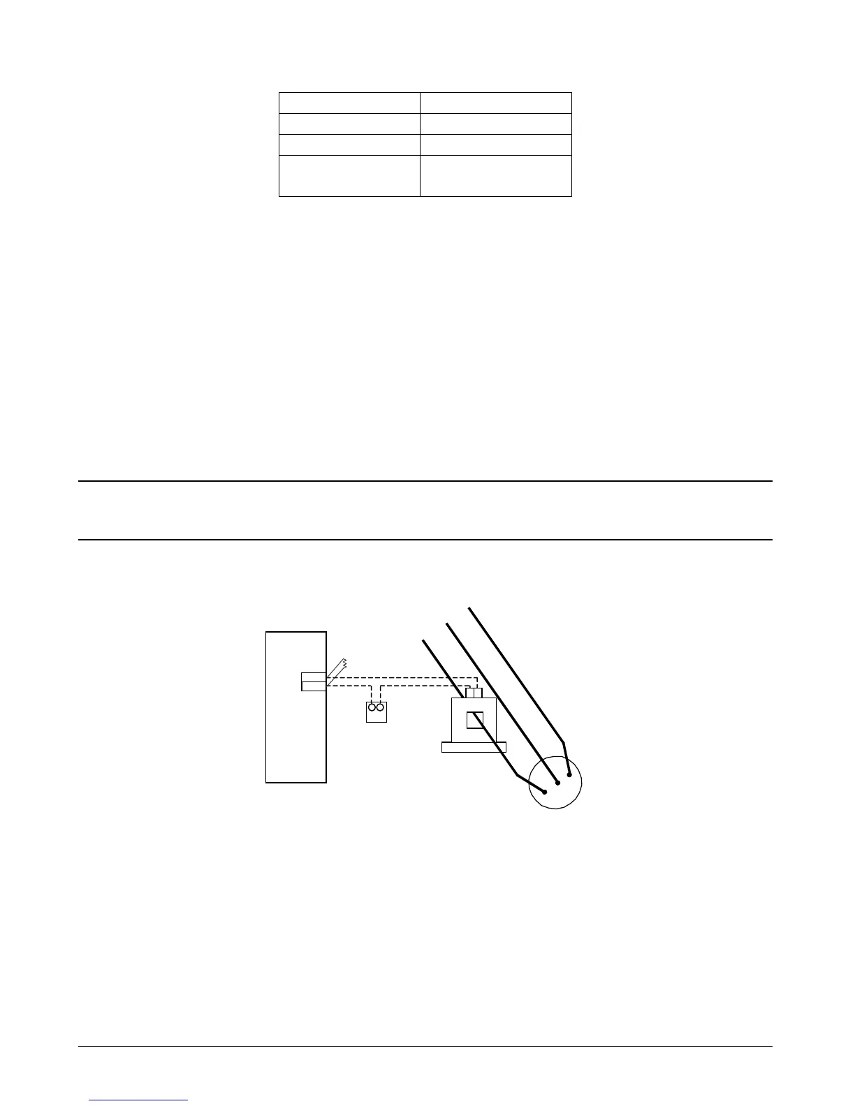
Figure 32. Measuring Compressor Amps with a Current Output Current Transducer
Current Transducer
with 4-20 mA Output
Compressor
+ -
Hardwired Chiller’s
Remote I/O Module
AI #1
11-(Y)
10-(0)
- +
24 VDC
Power Supply
499 Ω Resisto

 Loading...


