Vacuum control
44
Pneumatic system
Introduction of New Generation of 4-Cylinder Inline Engines, OM 651
q
Vacuum control
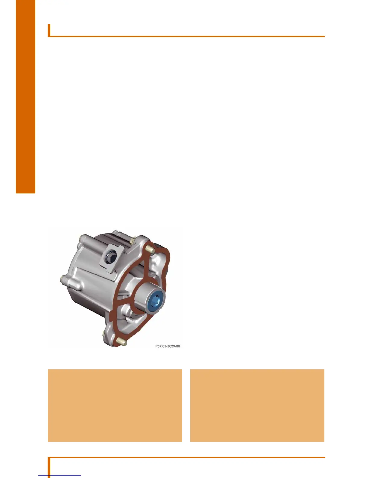
The vacuum pump is driven indirectly via the oil pump
drive. It generates vacuum pressure and is connected
to the vacuum system via its central line to the brake
booster. The system incorporates:
• Vacuum reservoir
• Wastegate control pressure transducer
• Boost pressure control flap pressure transducer
• EGR cooler bypass switchover valve
• Charge air bypass flap switchover valve
• Coolant pump switchover valve
The following components are actuated by a pulse
width modulated signal:
• Boost pressure control flap pressure transducer
– The boost pressure control flap opens
steplessly
and controls the exhaust flow
between the high-pressure turbocharger and
low-pressure turbocharger.
• Wastegate control pressure transducer
– The wastegate opens steplessly. Part of the
exhaust flow
is directed past the low-pressure
turbocharger to the exhaust system.
• Charge air bypass flap switchover valve
– The bypass flap opens and relieves the load on
the high-pressure
turbocharger.
• EGR cooler bypass switchover valve
– The bypass upstream of the EGR cooler opens
and the exhaust flow is directed through the
EGR cooler.
• Coolant pump switchover valve
– The coolant flow to the coolant pump is closed
off by the mechanical control components
integrated in the coolant pump.
a Risk of engine damage
When vacuum lines are installed, attention must
be paid to the respective color coding of the
vacuum line and of the vacuum unit otherwise
there is a risk of engine damage.
i Note
Ventilation of the pressure transducers for waste-
gate control and for the boost pressure control
flap takes place via the same vent filter.
Vacuum pump
 Loading...