OUTBOARD INSTALLATION
104
Description Nm lb. in. lb. ft.
Nylon insert locknut "b" 27 20
Nylon insert locknut "e"
Tighten until it seats, then back off 1/4
turn
Assemble steering link rod to steering cable with two flat washers
and nylon insert locknut. Tighten locknut until it seats, then back
nut off 1/4 turn.
Assemble steering link rod to engine with special washer head bolt,
locknut and spacer. First torque bolt, then torque locknut to
specifications.
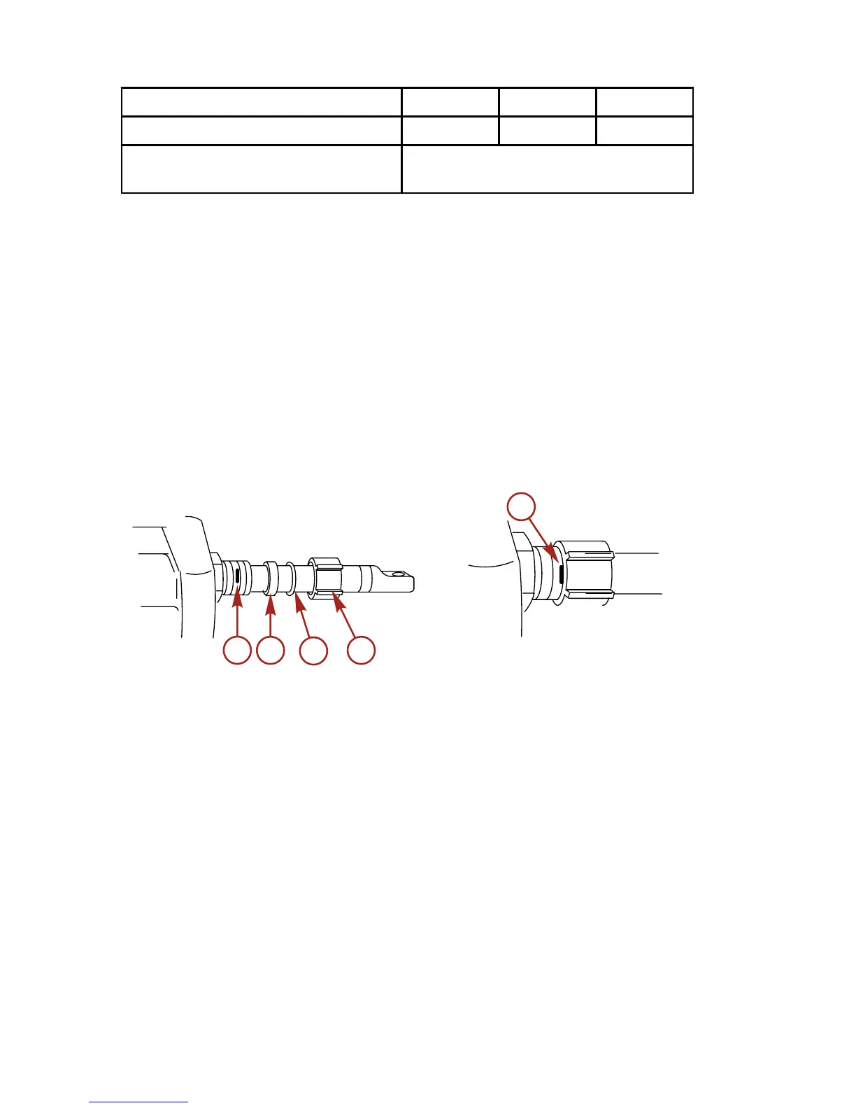
Steering Cable Seal
1. Mark tilt tube 6.4 mm (0.25 in.) from end. Install seal
components.
2. Thread cap to the mark.
a - 6.4 mm (1/4 in.)
b - Plastic spacer
c - O‑ring seal
d - Cap
Fuel Hose Connection ‑ Remote Control Models
REMOTE FUEL HOSE SIZE
Minimum fuel hose inside diameter (ID) is 8 mm (5/16 in.). Use a
separate fuel hose/fuel tank pickup for each engine.

 Loading...