Doc# 1231558 • REV C (November 2017) Page 3 of 20
1.3 Primary Variables Aecng 5550 Operaon
The required seismic acceleraon to move the 5550 or 5550G mechanical switch from its un-
tripped posion to its tripped posion is a funcon of three variables as detailed in secons
1.3.1 through 1.3.4.
1.3.1 Variable #1 – Spring Force Direcon
The movable trip plate mass inside the switch housing is
free to move on an essenally friconless pivot, and is
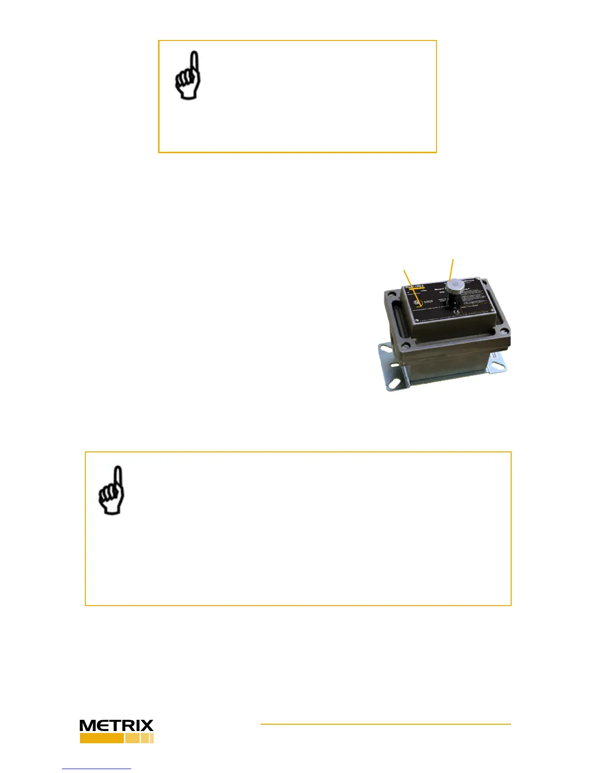
restrained in its untripped posion by a spring. By turning
the setpoint adjustment screw (Figure 3), changes are made
to the spring’s direcon, and to a much lesser extent, its
tension. Thus, the spring mechanism exerts an essenally
constant force on the trip plate and turning the setpoint ad-
justment screw changes the direcon of this force. Turning
the setpoint screw clockwise (CW) aligns the spring force
more fully in the untripped direcon (below the pivot – see
Figure 1), making it more dicult to trip the device. Turn-
ing the setpoint screw counter-clockwise (CCW) does the
opposite, making it easier to trip the device.
SETPOINT
ADJUST
RESET PLUNGER
FIGURE 3: MODEL 5550 setpoint
adjustment and manual reset.
NOTE: Metrix Mechanical Vibraon Switches
are not intended for use on high-speed tur-
bomachinery or on machines where changes in
seismic acceleraon smaller than 1G must be
reliably detected. Instead, Metrix oers more
sophiscated electronic vibraon sensing soluons that
are beer suited for such applicaons.
NOTES:
1. Turning the screw too far in the counter clockwise (CCW) direcon will eventu-
ally pull the spring past the over-center locaon and cause the switch to snap
into the tripped posion without any external ineral excitaon. When adjusted
in this manner, the switch cannot be reset from its tripped posion. Also, the
nature of this over-center mechanism can cause it to be very unstable when adjusted too
close to its equilibrium locaon, resulng in false trips.
2. The setpoint adjustment screw on the model 5550G switch is not externally accessible.
The cover must be removed. Do not remove the cover while energized circuits are pres-
ent in hazardous areas
1.3.2 Variable #2 – Switch Orientaon
Depending on how the switch is oriented, gravity will act on the trip mechanism’s mov-
able mass to either add to or subtract from the spring force. For both model 5550 and
5550G switches, the switch orientaon is the direcon in which the cover faces. With the
switch oriented horizontally (Figure 4A), the eects of gravity will be negligible and only
 Loading...
