Doc# 1231558 • REV C (November 2017) Page 7 of 20
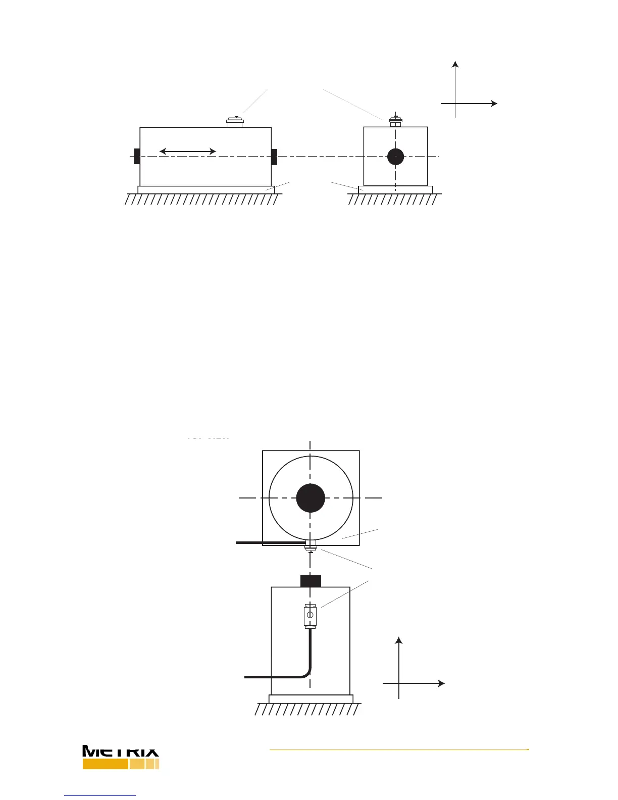
Figure 7: Horizontal machine showing verctal 5550 mounng orientaon (not recommended).
SHAFT CENTERLINE
5550 MOUNTING LOCATION
BASEPLATE
SHAFT Z AXIS
(AXIAL)
CONDUIT
END VIEW
SIDE VIEW
Shaft Radial Y Axis
Shaft Radial X Axis
SHAFT CENTERLINE
2.6 Vercal Machines
Figure 8 shows the preferred installaon for a vercal machine. The switch is mounted
horizontally and with its sensive axis poinng directly at the sha.
In contrast, Figure 7 shows the switch mounted vercally, which is not recommended.
Because most vercal machines (like horizontal machines) are rigidly xed by a baseplate
or other mounng that constrains them from vibrang in the vercal direcon, aligning the
switch’s sensive axis in the vercal direcon aligns it in the direcon of least vibraon.
Instead, mount the switch as shown in Figure 5 to ensure that radial (not axial) vibraon is
detected. Mount the switch as shown in Figure 7 only when the machine actually vibrates
more in the vercal than horizontal direcon, or when the 2 g /24 V reset coil opon is used
(see note in secon 2.4).
SHAFT CENTERLINE
CONDUIT
BASEPLATE
5550 MOUNTING LOCATION
WITH CONDUIT FITTING
FACING DOWN
BASEPLATE
SHAFT Z AXIS
(AXIAL)
CONDUIT
SIDE VIEW
NOTE: A drain hole at low point is
recommended to allow accumulated
moisture to exit (except in
explosion-proof installations)
Shaft Radial Y Axis
Shaft Radial X Axis
Figure 8: Vercal Machine showing horizontal 5550 mounng orientaon and recommended locaon
 Loading...
