Doc# 1231558 • REV C (November 2017) Page 2 of 20
1. PRINCIPLES OF OPERATION
1.1 Overview
Model 5550 and 5550G Mechanical Vibraon Switches oer basic protecon against gross
changes in structural seismic acceleraon. The two units are idencal internally and dier
only in their enclosure style and external access to adjustments. The 5550G is used for haz-
ardous area applicaons requiring gas group IIC approvals, but has no externally accessible
adjustments. The 5550 has externally available setpoint adjustment and reset facilies, and
can be used for applicaons up to gas group IIB + hydrogen. Refer to hazardous area instal-
laon manuals M8905 (model 5550) and 100356 (model 5550G) for addional informaon.
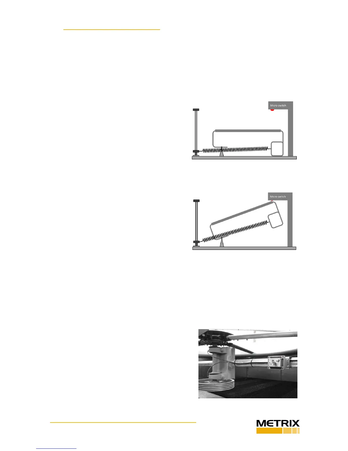
The operang mechanism is purely mechanical and
consists of a tension spring aached to a pivong
plate on an over-center fulcrum – magnets are not
employed. Normally, this plate is in an untripped
posion (Figure 1A). However, in the presence of
sucient seismic acceleraon (whether vibratory
or impact), the trip plate will pivot beyond this
over-center posion, snapping to a stable tripped
posion (Figure 1B) where it contacts an internal
micro-switch relay, changing the state of the relay.
This relay is available for external wiring connec-
ons where on/o changes in electrical connuity
can be used to trip the machine and/or annunci-
ate excessive vibraon.
Once the switch has assumed its tripped posion,
it must be reset manually by means of the external
reset plunger (5550 only), or by means of a remote
electrical reset (standard on 5550G, oponal on
5550). The remote reset capability can also be
used as a startup delay to hold the switch in an
untripped state for as long as coil excitaon is sup-
plied – up to 30 seconds (the maximum duraon
is governed by a non-adjustable, factory-installed
thermistor circuit). The startup delay feature is useful during machinery startup when vibra-
on in excess of the normal trip seng may be temporarily incurred.
1.2 Typical Applicaon
The model 5550 and 5550G mechanical vibraon switches are typically used on cooling
tower fans and mounted such that loss of a blade will result in signicant structural accelera-
on at the switch mounng locaon (Figure 2).
The switch may be used on other types of machin-
ery as well, but care must be taken to ensure that
adequate change in acceleraon between “normal”
and “malfuncon” condions will exist at the switch’s
mounng locaon. The switch is not designed to reli-
ably trip for acceleraon levels below approximately
1 g (9.8 m/s
2
), or when less than 1 g exists between
a machine’s normal running vibraon levels and mal-
funcon vibraon levels.
Figure 2: Typical 5550 installaon on
cooling tower fan support strut.
Figure 1A: 5550 mechanical switch trip
mechanism in untripped posion. Micro-
switch (red) is not actuated.
Figure 1B: 5550 mechanical switch trip
mechanism in tripped posion. Micro-
switch (red) is actuated.
 Loading...
