Doc# 1231558 • REV C (November 2017) Page 6 of 20
SHAFT CENTERLINE
CONDUIT
5550 MOUNTING LOCATION
WITH CONDUIT FITTING
FACING DOWN
BASEPLATE
SHAFT Z AXIS
(AXIAL)
CONDUIT
END VIEW
SIDE VIEW
NOTE: A drain hole at low point is
recommended to allow accumulated
moisture to exit (except in
explosion-proof installations)
Shaft Radial Y Axis
Shaft Radial X Axis
SHAFT CENTERLINE
SHAFT CENTERLINE
CONDUIT
5550 MOUNTING LOCATION
WITH CONDUIT FITTING
FACING DOWN
BASEPLATE
SHAFT Z AXIS
(AXIAL)
CONDUIT
NOTE: A drain hole at low point is
recommended to allow accumulated
moisture to exit (except in
explosion-proof installations)
SHAFT CENTERLINE
P
Shaft Radial Y Axis
Shaft Radial X Axis
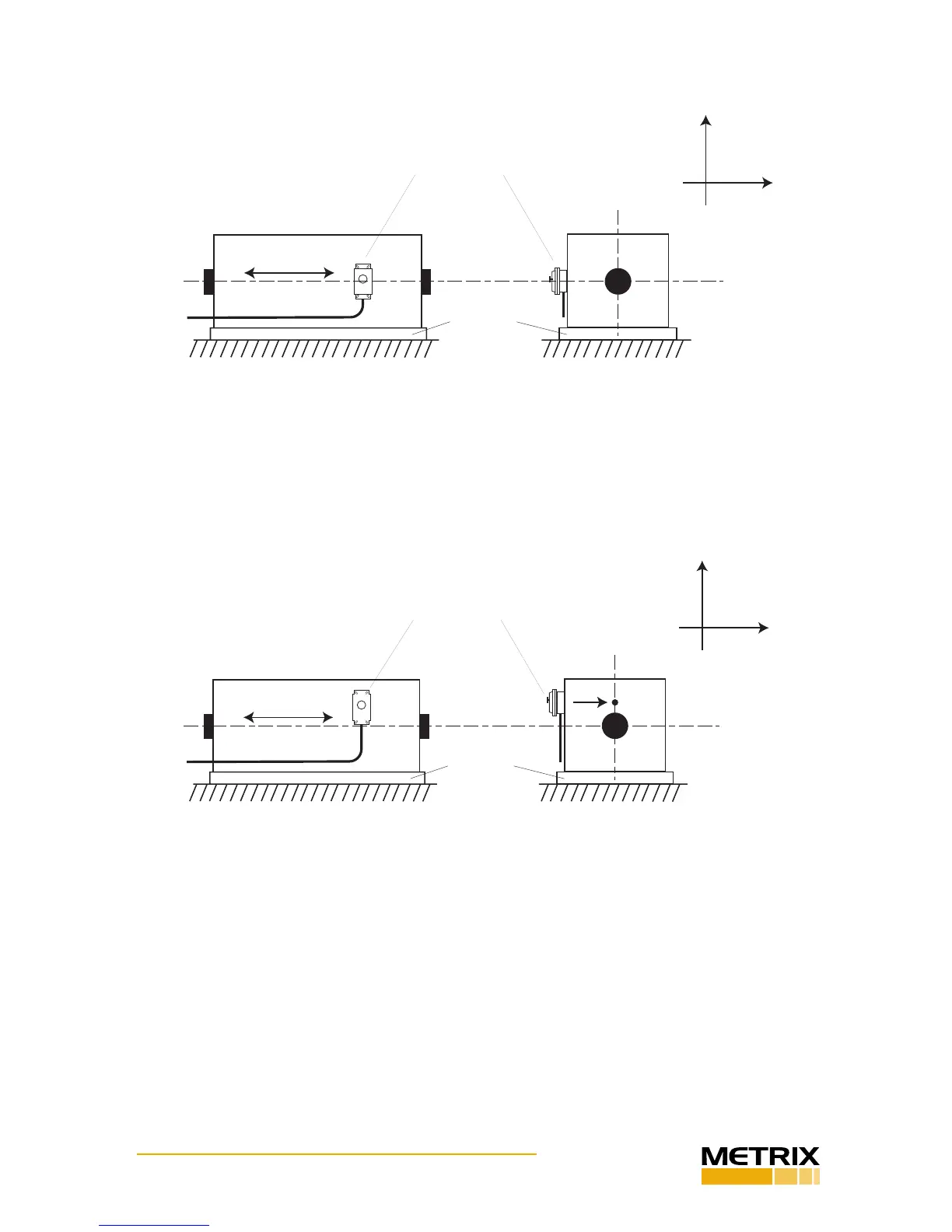
Figure 5: Horizontal machine showing horizontal 5550 mounng orientaon and preferred locaon.
Conduit ng faces down to allow drainage of any condensaon.
Figure 6: Horizontal machine showing horizontal 5550 mounng orientaon and alternate locaon.
Conduit ng faces down to allow drainage of any condensaon.
Figure 7 shows the same horizontal machine as in Figures 5 and 6, but with the switch ori-
ented vercally. As noted in Secon 2.4, a vercal orientaon of the switch is discouraged
because machines will generally experience less vibraon in the vercal direcon than in
the horizontal direcon, and the switch will be less eecve. Metrix does not recommend
installaon as shown in Figure 7 unless the machine truly experiences more vibraon in the
vercal direcon than in the horizontal direcon, or the 2g / 24V reset coil opon is being
used (see note in Secon 2.4).
 Loading...
