10
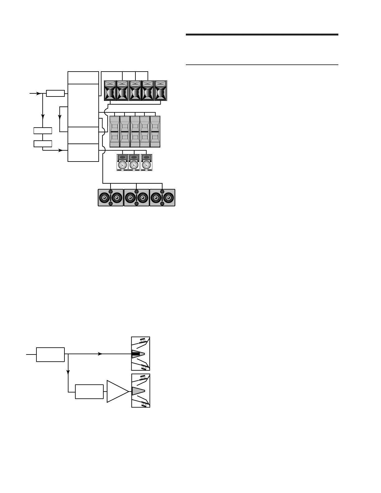
We recommend that the entire system be measured,
phase-aligned, and equalized using the SIM System II
Sound Analyzer and CP-10 Parametric Equalizer.
650-P Subwoofers
CQ Down-fills
DS-2P Mid-Bass
MSL-4 Mid-Hi
Input Mid-Hi
Output
DS-2
Output
Loop
Sub
Output
Input Output
LD-1A
Delay
CP-10 EQ
CP-10 EQ
CH 1
CH 3
Input Output
CH 5
Set the CQ to the opposite polarity to the MSL-4 and DS-2P.
The polarity of the 650-P depends on the height and
distance of the measurement position from the the flown
and subwoofer systems.
DS-2P and DS-2
Although it is preferable to employ the DS-2P in a
completely self-powered system, the DS-2P can be used
with the DS-2 externally amplified mid-bass speaker if:
• the D-2 CEU is set to the maximum output level;
• the DS-2 amplifier is set to 26 dB gain;
• the DS-2P is set to the same polarity as the DS-2
amplifier.
26 dB gainlevel control
at maximum
CP-10 EQ
D-2
CEU
Amplifier
DS-2
DS-2P
Set the DS-2P and the DS-2 amplifier to the same polarity.
Driver Troubleshooting
Troubleshooting with TPL
The TPL LED can indicate serious driver problems, if
interpreted correctly. If one DS-2P in a system exhibits
substantially more TPL activity than others receiving
the same audio signal, then one or both drivers in that
unit may have a short circuit. This is a potentially
dangerous condition for the electronics; shut the DS-2P
down immediately.
The TPL circuit does not activate if there is no power
dissipation in the driver, regardless of the input signal
level. Therefore, if all DS-2Ps in a system receiving the
same audio signal exhibit TPL activity except one, then
that unit may have an open voice coil; disconnect it and
contact Meyer Sound for repair information.
NOTE: The Remote Monitoring System (RMS) provides
precise information about peak power, peak voltage, and
average voltage (VU) for each amplifier channel, enabling
a more complete driver diagnostic than the TPL LEDs.
Contact Meyer Sound for more information about RMS.
Driver Replacement
To determine whether a driver is functioning properly,
or replace a damaged driver, contact Meyer Sound to
obtain the
Low Driver Inspection and Evaluation
Procedure for Self-Powered Series Products
(part #
17.010.120.01).
Verifying Driver Polarity
Incorrect driver polarity impairs system performance
and may damage the drivers. All Meyer loudspeakers
are shipped with the drivers in correct alignment. How-
ever, if the driver or circuit wiring has been removed or
disassembled in any loudspeaker in a system for any
reason, it is essential to check the polarity between
drivers in the same cabinet and between adjacent loud-
speakers.
We do not recommend using phase poppers to analyze
driver polarity. The phase response for all drivers varies,
to some degree, over the frequency range in which it
operates. Since the phase popper, a popular but inaccurate
tool, does not discern variations in phase response with
respect to frequency, it provides no useful information
about the phase response through the crossover, the
most important consideration for determining correct
driver polarity.
 Loading...