9
Complete Systems
The following Meyer speakers are mentioned in the
example applications.
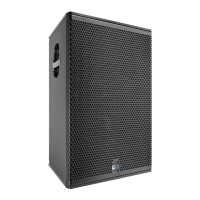
MSL-4, CQ Self-powered mid-hi speaker
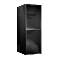
650-P Self-powered subwoofer
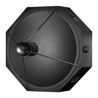
DS-2 Externally amplified mid-bass speaker
The Meyer self-powered speakers listed above have a
loop connection to send the input signal to another
speaker. Full-range signals may be applied to all Meyer
self-powered subwoofers because they have built-in
active crossovers that filter mid-hi frequencies.
LD-1A with MSL-4, DS-2P, and 650-P
Although the DS-2P can be used as a stand-alone sub-
woofer, it is most effectively employed with the 650-P to
enhance low frequency (LF) power and clarity. The LD-1A
is an effective tool to control this configuration containing
three subsystems and two crossover points.
With the DS-2 & Sub Crossover switch in, the DS-2 and
Sub outputs each receive signals optimized for the
frequency response capabilities of the DS-2P and 650-P.
The MSL-4 is driven from the CH 1 Mid-Hi output with
the Lo Cut filter in to minimize the overlap in frequency
response with the DS-2P and 650-P. Set the 650-P to the
opposite polarity to the MSL-4 and DS-2P.
MSL-4
DS-2P
CH 1 DS-2
650-P
CH 1 Sub
CH 1 Mid-Hi
Input CH 1
LD-1A
Line Driver
Set the 650-P to the opposite polarity to the DS-2P and
MSL-4.
LD-1A with MSL-4, DS-2P, CQ, and
650-P
This example shows the LD-1A integrating a complete
system of self-powered speakers for a large venue.
Although the diagram shows half of the system with
channels 1, 3, and 5, channels 2, 4, and 6 can be used with
identical connections for the other half. The MSL-4, DS-2P,
and CQ arrays are flown; the 650-Ps are on the floor.
The CH 1 Mid-Hi and CH 3 outputs drive the inner three
and outer two speakers of the MSL-4 array, applying
appropriate levels for speakers directed at different
distances. The diagram shows the additional mid-hi
output created by connecting the CH 1 Loop to the CH 3
input. Using a Y-connection at the CH 1 input (as shown for
the down-fills) accomplishes the same signal routing.
The Lo Cut and Array EQ switches for both channels
should be in. The Lo Cut filters eliminate the LF rise
caused by the frequency response overlap between the
MSL-4 and DS-2P/650-P systems. The Array EQ filters
minimize the MSL-4 array’s low-mid rise.
The CH 1 DS-2 and Sub outputs drive the DS-2P and
650-P systems with the DS-2 & Sub Crossover switch in.
Set the MSL-4 and DS-2P to the same polarity. The
polarity of the 650-P depends on the height and distance
of the measurement position from the subwoofer and
flown systems.
CH 5 controls the CQ down-fill system. Since the main
system is more powerful than the down-fill system to
project farther into the venue, the main system is audible
in the down-fill’s coverage area. To insure that the
speakers combine properly in the intersecting coverage
area:
• Set the CQ to the opposite polarity to the MSL-4 to
phase align the mid-hi frequencies and minimize
the MSL-4’s LF down-lobe.
• Use the CH 5 Lo Cut filter to eliminate the LF rise
caused by the overlap in frequency response with
the 650-P and DS-2P systems.
• Delay the down-fill to compensate for the propa-
gation delay between the down-fill and main
systems in the intersecting coverage area.
 Loading...