12
Array Design
Array Design for Low Frequencies
Although the DS-2P is a called a mid-bass speaker, it still
functions in the frequency realm of a subwoofer, especially
when used as a stand-alone subwoofer without the 650-P
or PSW-2. Subwoofer and mid-hi speaker array design
differ because frequencies below 125 Hz are mostly
omnidirectional; directionality increases with frequency.
However, when several subwoofers are arrayed, the
low frequencies can be focused. This section introduces
some of the fundamental concepts for designing sub-
woofer arrays.
The coverage patterns of two DS-2Ps in a horizontal
array interfere with each other such that the horizontal
coverage narrows, without affecting the vertical coverage.
A vertical array of two DS-2Ps narrows the vertical,
without affecting the horizontal coverage. Due to the
larger distance between drivers in vertical arrays, the
vertical coverage narrows at a more significant rate than
does the horizontal coverage for horizontal arrays,
given the same array size.
Increasing the number of horizontal or vertical DS-2Ps
in the array increases the corresponding H or V LF
directional control. A properly designed vertical array steers
low frequencies to include balconies and upper tiers,
while a horizontal array focuses low frequencies for
long throw distances without interacting with the walls.
One of the most important factors governing LF response is
speaker placement relative to adjacent surfaces. The DS-2P
gains significant LF power by coupling with nearby
floors and walls. Half-space loading describes a speaker
coupling with one surface. Speakers placed on the floor
benefit from half-space loading, while flown speakers in
free-space (without a nearby wall or ceiling) do not. In
general, subwoofers in half-space generate twice the
SPL (+6 dB) compared to the same number in free-space.
NOTE: The trapezoidal shape of the DS-2P does not
represent the horizontal coverage area of the speaker.
DS-2P Coverage and Maximum SPL
A series of outdoor tests was conducted at Meyer Sound
to determine the coverage angle and on-axis SPL for
arrays with one row with up to six speakers. The mea-
surements were conducted at a distance of 8 m with half-
space loading; on-axis SPL values were interpolated
from 8 m to 1 m. The coverage angle for the array is the
result of averaging the –6 dB points from 60 to 160 Hz.
Since the DS-2P’s horizontal coverage angle is wide
(140°), splay angles larger than 15° are not often used.
The 15° angle is optimal since it combines substantial
SPL addition with a narrowing of the horizontal coverage.
The 15° angle also corresponds to tight-packing DS-2Ps
together along the edges of the enclosure, making array
construction particularly convenient, especially for
rigging clusters.
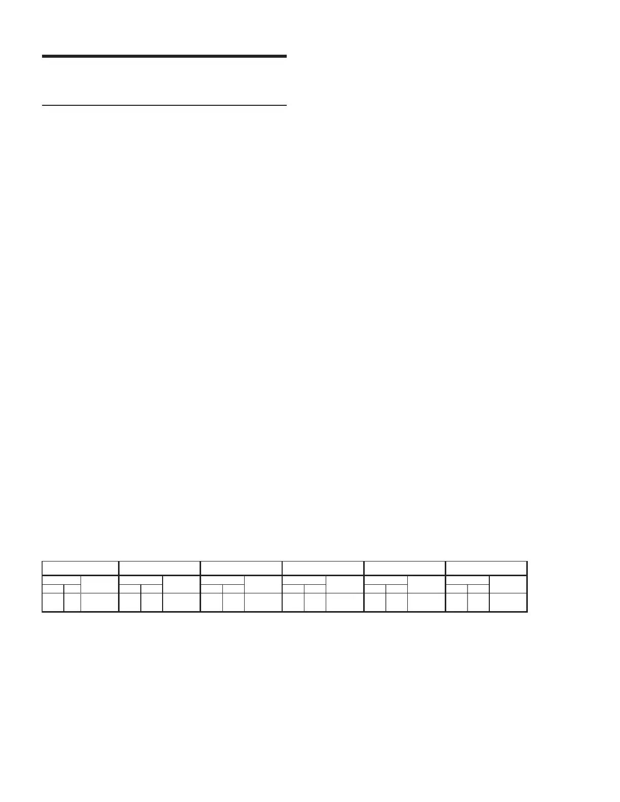
The following table shows the SPL and coverage areas
for horizontal arrays with up to 6 DS-2Ps. The splay
angle refers to the angle between cabinet centers.
If this information does not address your application
requirements, contact Meyer Sound to obtain additional
information on array design.
1 2 @ 15° 3 @ 15° 4 @ 15° 5 @ 15° 6 @ 15°
Coverage Max Peak Coverage Max Peak Coverage Max Peak Coverage Max Peak Coverage Max Peak Coverage Max Peak
H V dB SPL H V dB SPL H V dB SPL H V dB SPL H V dB SPL H V dB SPL
140 120 141 120 120 148 110 120 150 100° 120 149 90 120 153 80 120 154
DS-2P Horizontal Array Coverage and Maximum SPL
 Loading...