14
4.8 ELECTRICAL CONNECTION
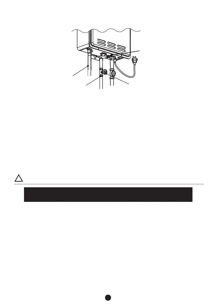
4.7 WATER CONNECTIONS
Ɣ
Ɣ
Ɣ
Ɣ
Ɣ
Ɣ
Ɣ
Ɣ
Ɣ
Ɣ
Ɣ
COLD WATER
INLET
GATE OR BALL
VALVE ON INLET
FILTER AND
DRAIN PLUG
WARNING
Do not reverse the hot outlet and cold supply line connections to the water heater as this
will cause your heater to operate improperly.
!
HOT WATER
OUTLET
The water heater must be electrically grounded. Do not attach the ground wire to either the gas or
water piping.
The water heater requires an AC 240V 50Hz electrical power supply and draws a current of 0.8A.
The weather-proof power point should be no more than 1 meter from the base of the water heater
for easy access.
Install a power switch so that the electrical power can be switched off if necessary.
If the cord supplied with this appliance must be replaced, it must be replaced with the correct
appliance wiring material supplied by the Manufacturer.
When servicing or replacing parts within the water heater, label all wires prior to disconnection to
facilitate an easy and error free reconnection. Verify proper operation after servicing
All pipes, pipe fittings, valves and other components, including soldering materials, must be
suitable for potable water systems.
A manual shut off valve must be installed on the cold water inlet to the water heater between the
main water supply line and the water heater.
Only a gate valve or a ball valve is to be used on the cold water supply.
Check the cold water pressure. If above 1000 kPa an approved limiting valve must be fitted.
Before installing the water heater, flush the water line to remove all debris, and after installation
is complete, purge the air from the line. Failure to do so may cause damage to the heater.
There is a wire mesh filter to discourage debris from entering your heater. Clean filter after initial
installation to ensure no debris from the pipe work has clogged it.
NOTE: M20 UNIT SHOWN
IN EXAMPLE
 Loading...