V6 VRF 50Hz
65
Part 5 - Electrical Components and Wiring Diagrams
3 Compressor Inverter Module
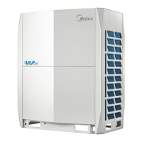
Layout 3.1.1
Figure 5-3.1: Compressor inverter module components
LED indicators LED1 and LED2 3.1.2
Table 5-3.1: LED indicators LED1 and LED2
LED indicator function and status
Inverter module operating indicator. Continuously on if the compressor is running normally and
flashing if an inverter module error has occurred
1
.
Inverter module error indicator. Continuously on if an inverter module error has occurred
1
.
Note:
1. If an inverter module error occurs, refer to Part 6, “Xh4 Troubleshooting”. The error code is displayed on the digital display.
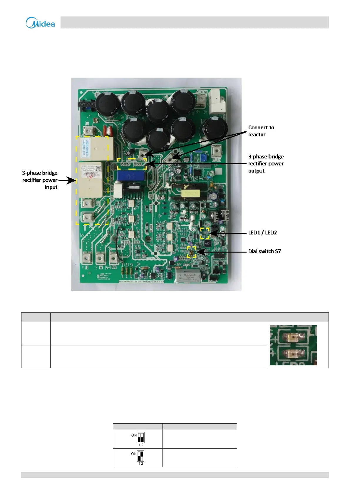
Dial switch S7 setting 3.1.3
Dial switch S7 is used to set compressor inverter module A/B address. The compressor inverter module A/B location refers
to the wiring diagram.
0 for compressor inverter module A
1 for compressor inverter module B

 Loading...