30-
Figu
2HP
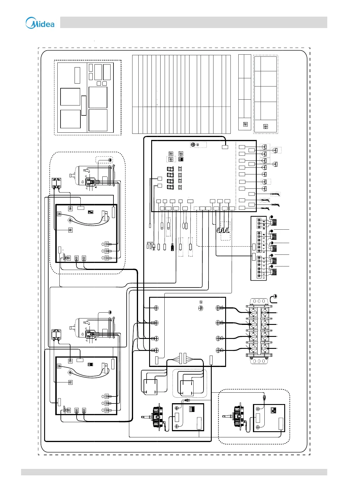
e5‐4.2:30‐32
N_out
RA
CN4
N_out
RB
CN4
CN10
CN10
Red(Black)
B
l
u
e
White
Red(Black)
Pwiringdiag
CN5
P_out
CN3
N_
i
n
CN1
P_in
U
V
w
S7
CN6
CN7
CN11
L1
L2
L3
CN5
P_out
CN3
N_
i
n
CN1
P_in
U
V
w
S7
CN6
CN7
CN11
L1
L2
L3
1
ON
2
ON
ck
ck
L8
Red
Black
B
l
u
e
C
o
m
p
r
e
s
s
o
r
Red(Black)
White
B
l
u
e
C
o
m
p
r
e
s
s
o
r
White
B
l
u
e
Red(Black)
Red
Black
B
l
u
e
XT1
RB RA
Main
board
AC filter
board
Up layer
Comm. board
CN2
CN2
Black Blue
am
U
V W
CN8(CN9)
IC17
COMP A
U
V W
IC17
COMP B
CN12 CN13 CN14
CN12 CN13 CN14
Black
Bl
Bl
Red
Black
B
l
u
e
Red
Black
B
l
u
e
BR1
BR2
C
o
m
p
r
e
s
s
o
r
d
r
i
v
e
b
o
a
r
d
A
C
o
m
p
r
e
s
s
o
r
d
r
i
v
e
b
o
a
r
d
B
DC fan drive
board A
DC fan drive
board B
Down layer
PCBA Layout
Brown
CN8(CN9)
+
-~
~
BR1
TP1-PRO
TP2-PRO
L-PRO
L3’
L1’
L2’
L3’
N’
FAN A
Red White Blue
Red White Blue
Black
Red
B
l
u
e
H-PRO
FAN A/B
EEVA/EEVB/EEVC
BR1/BR2
COMP A/COMP B
DC Fan
Electronic expansion valve
Inverter compressor A/B
CODE NAME
Single-phase Bridge Rectifier
L-PRO
CN19
H-PRO
CN18
DSP1 DSP2
CN17
H-YL1
7C1
OKUPMENU DOWN
ENC3
S12
IN_NUM
TF1
T7C1
N4
T7C2
CN5 CN8
T6A
T7C2
CN1
T4 T3
CN3
TF2
CN3_1
TF2
CN15
T6A
T4
T3
ENC2
POWER
CN12
CN9
CN10
CN11
CN3
N
P
H-YL1
CN31(CN32)
1
ON
2
3
+~
BR2
CN32(CN31)
ENC1
NUM_ S
(Left)
Red
B
l
u
e
B
l
u
e
Black
DC fan drive
ST1
H-PRO/L-PRO
H-YL1
RA/RB
IC17
SV2/SV4-SV9
HEATA/HEATB
4-way valve
Reactance
Current sensor
High/Low pressure ON/OFF switch
High pressure sensor
ran
case
ea
er
Solenoid valve
L8
Current sensor
CN100
N8_1
6B
C
E
CN27
O-FAN
CN26
O-C
CN20
O-O
EEVA
T6B
CN25
N
CN5
CN51
L1
L2
L3
CN6 CN7 CN8
1
ON
2 34
C
N
1
(
C
N
4
)
-~
SW1
B
l
u
e
Black
Main board
T3
T4
T7C1/T7C2
TF1/TF2
Plate heat exchanger cooling refrigerant
inlet/outlet temperature sensor
Main exchanger pipe temperature
sensor
T6A/T6B
Outdoor ambient temperature sensor
Discharge temperature sensor
Inverter-module heatsink temperature
sensor
CN21(CN22)
CN28
O-D
FAN B
C
C
CN
CN
CN85
CN83
CN46
CN44
CN43
CN47
CN67
CN66
70
VA
CN72
EEVC
EEVC
CN71
EEVB
EEVB
ST1 SV4 SV5 SV7 SV8A SV9
SV6 SV8BHEATB
HEATBHEATA
HEATA
CN30
CN82
N-ON
CN41
SV2
(Right)
Red
Black
White
B
l
u
e
Red
Black
White
B
l
u
e
Black
Black Black Black
capacity
setting
ENC2 B
30HP
C
32HP
ENC2
POWER
Comm. board
XT1
TP1/TP2-PRO
Terminal block
Discharge temperature ON/OFF switch
CN3
C
N
1
(
C
N
4
)
N
P
ST1
84
45
7_1
6_1
SV4 SV5 SV7 SV8A SV9
SV6
SV8B
HEATA
HEATA
HEATB
H EAT B
ABC
XT1
N
SV2
1
ON
2 34
SW1
DC fan drive
board B
CN4 CN6
To
kilowatt-
To
centrali-
To
indoor units
To
outdoor
Outdoor unit
address
setting
ENC1 0
Master
unit
(Factory
setting)
12
ENC1
NUM_S
Slave
unit 1
Slave
unit 2
6 VRF 5
16027000007528
ENC1 is available in multi outdoor unit system.
The dotted frame section is use by some models.
This connection diagram is for reference onl y.
Please refer to the actual product.
hour
meter
controller
-
cation
bus
-
unication bus
Hz
67
Part 5 - Electrical Components and Wiring Diagrams

 Loading...