V6 VRF 50Hz
95
Part 6 - Diagnosis and Troubleshooting
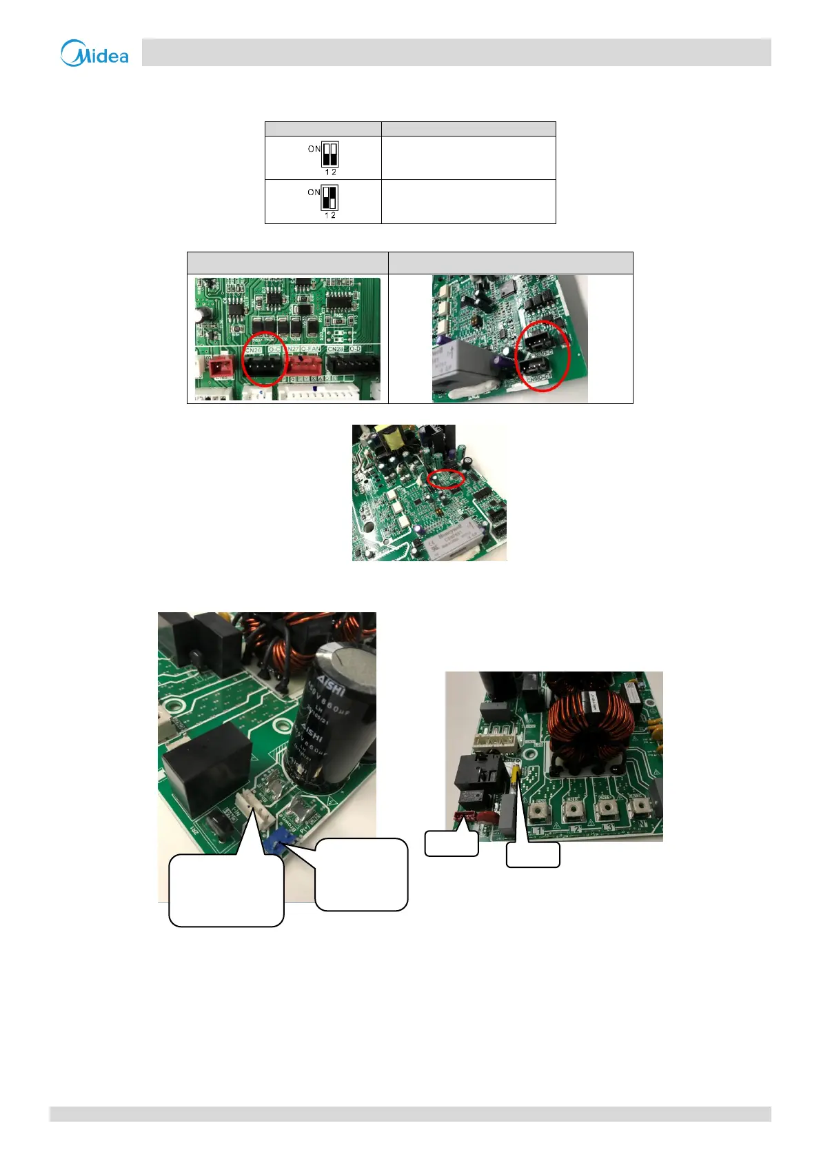
Notes:
1. Compressor inverter module address is set through dial switch S7 on the inverter module. The compressor inverter module A/B location refers to the
wiring diagram.
0 for compressor inverter module A
1 for compressor inverter module B
2. Communication wire from outdoor main PCB CN26 to inverter module CN8/CN9.
Communication port CN26 on main PCB
Communication port CN8/CN9 on inverter module
3. LED1/2 on inverter module
4. Check the power supply for the compressor inverter module, port CN41 on filter board, the normal voltage should be DC310V; check the high pressure
switch connection port CN61 on filter board, the normal resistance should be zero; Check the single phase bridge and fuse on filter board; check the
connection cable from ODU main PCB port CN82 to filter board port CN30 which is DC310V power control port.
SMPS of
Compressor inverter
module
CN61 High
pressure switch
connection port

 Loading...