7
TO AVOID DAMAGE TO SENSITIVE
ELECTRONICS, REMOVE THE COV ER
FROM THE ECC CAREFULLY.
2.6.1 Inst allation of Input/Output Comma nd
Signal Wiring
1. Uns crew the ECC cover by turning it counter-
clockwise (as viewed fro m the top ). Lif t th e
cover straight off and away.
IMPROPER CONNECTION OF THE
COMMAND LIN ES CA N CAU SE DA M-
AGE TO THE ECC. USE ONLY 300
VOLT, 105°C RATED WIRE , MINIMUM
22 AWG, MAXIMUM 14 AWG.
2. Maintain integrity of safety approv als us ing
only 300 volt, 105° C (UL 1213 or equiv.) rated
insulation. Maintain CE immunity ratings, using
shielded cable inside of conduit.
3. Feed fo ur (1 4 to 2 2 A WG) shield ed wir es
through appropriately r ated con duit b ushing
inserted into one of the conduit holes in base of
ECC. Ground shields for four wires to a good
chassis ground at control end.
4. Route wires to ECC keeping electrical interfer-
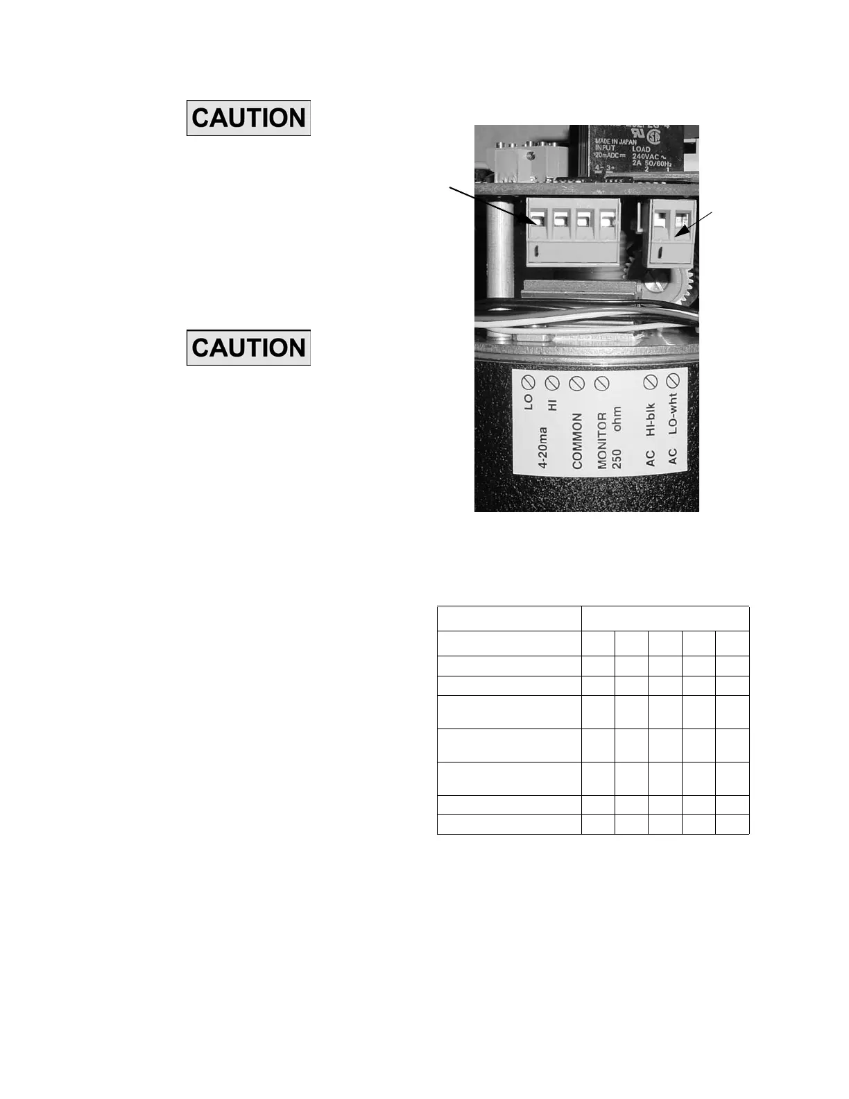
ence to a minimum. Carefully pull four-position
connector J5 from circuit board. Connect com-
mand signa l wir es to co nnector J5 (Figure 4
and 12 ). Re connect con nector J5 to circuit
board.
2.6.2 Input Signal
The input signal, used to control the ECC, can be
either 4- 20 mA or (1-5 VDC). A five-position Dip
switch, SW2 (F igure 11, located on the top of th e
circuit board) selects the control signal used by the
operator. The f actory se ts SW2 fo r the model
ordered and should not need changed. Position
1 (Table 10) of SW2 sets the input signal. Position
2 sets the movement of the ECC after unintentional
loss of the control signal. Position 3 and 4 sets the
ECC for use with a pump o r valve a nd should
always be set to 3- OFF and 4 -ON for the pum p
mode. Position 5 is not used.
Figure 4. Circuit Board Connectors J4 and J5
2.6.3 Feedback Output Signal
A position output, proportional to ECC po sition, is
used for remote position indication. A current of 4-
20 m A or a volt age of 1 -5 VDC is a vailable
between MONIT OR (J5- 4) and COMMON ( J5-3).
Feedback zero an d feed back sp an adju stments
(Figure 1 1) ar e p rovided to fine tu ne th e ou tput
(see calibration instructions). DIP switch SW3 (Fig-
Table 10. SW2 DIP Switch Settings
INPUT SWITCH POSITION
12345
Input Signal of 4-20 mA ON
Input Signal of 1-5 VDC OFF
Hold Position on Loss of
Control Signal
ON
Return to Lower Limit on
Loss of Control Signal
OFF
Pump Mode (limits abso-
lute)
OFF ON
Valve Mode (limits floating) ON OFF
Not Used NC
J4
J5
www.motralec.com / service-commercial@motralec.com / 01.39.97.65.10

 Loading...