1
SECTION 1
DESCRIPTION
1.1 GENERAL INFORMATION
In this age of so phisticated pr ocess control con -
cepts, many people are taking advantage of the lat-
est b reakthroughs in technology to up grade the ir
own equipment and systems. The Milton Roy Elec-
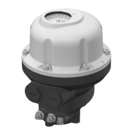
tronic Capacity Control (ECC) easily interfaces with
computerized process and process instruments, as
the ECC will adjust the output of a metering pump
from 0% to 100% in response to a 4 to 20 milliamp
or 1 to 5 VDC sig nal from a co mputer or othe r
source. This outstanding feature can be purchased
as an integral part of the pump, or it can be bought
separately and field installed. The ECC mounts to
the housing of the pump and operates in place of
the manual stroke adjustment.
1.2 PRINCIPLE OF OPERATION
The ECC allo ws remote adjustment of th e volume
of liq uid d elivered b y the metering p ump. Th is is
accomplished by utilizing a 4-20 mA command sig-
nal from a Milton R oy Remote Panel Mount
(ARPM-100/200) or Remo te W all Mo unt ( ARWM-
100/200) re mote controller (manual 33 90021000),
or a c ustomer’s cont rol system. I n a closed loop
control system, the ECC a ccepts the com puter o r
controller 4- 20 m A sig nal d irectly an d p rovides
immediate an d a ccurate co ntrol of the pum p flow
under varying process conditions.
When th e ECC re ceives the 4- 20 m A co mmand
signal, the dr ive mo tor responds by mo ving the
ECC to the required position. As the ECC moves, it
changes th e position of the pu mp’s str oke ad just
shaft, thu s altering th e pu mp’s flow rate. Refer to
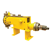
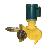
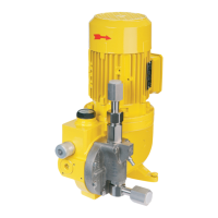
Table 1 wh ich list s r eference ma nuals containing
information on the stro ke ad just shaf t a nd pump
operation.
If th e pu mp flow r ate n eeds to be m onitored, th e
ECC then communicates its position by outpu tting
a nominal 4-20 mA or (1-5 VDC) signal. This signal
can be inter cepted an d tr anslated b y an ARPM-
100/200 or ARWM-100/200 or other user supplied
equipment to display the current ECC position.
1.3 SPECIFICATIONS
INPUT POWER
115 VAC, 50/60 Hz, 1 phase ±10% (standard)
220 VAC, 50/60 Hz, 1 phase ±10% (optional)
1 amp max
CONTROL SIGNAL INPUT
4-20 mA into 250 ohms impedance (standard)
Direct acting: 4-20 mA (see note below)
Split range: 4-12 mA, 12-20 mA
1-5 VDC 440K load, DIP selectable (optional)
NOTE
As supplied, the ECC is direct ac ting
(pump c apacity increases w ith increasing
input sign al to ECC) alth ough it m ay b e
converted to re verse a cting b y fo llowing
the procedure outlined in Section 3, “Oper-
ation”.
POSITION FEEDBACK OUTPUT
4-20 mA, max 500 ohm load (standard)
1-5 VDC, min. 25 0 o hms imp edance, DIP se lect-
able (optional)
Table 1. Stroke Adjust Shaft & Pump Opera-
tion Reference Manuals
PUMP MANUAL
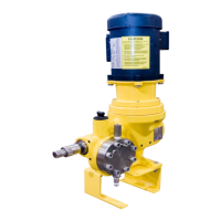
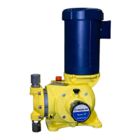
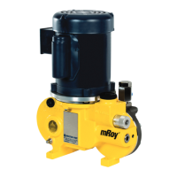
mRoy 3390047000
maxRoy B 3390005000
Milroyal C 3390009000
Milroyal B 3390066000
Milroyal D 3390010000
MacRoy G 3390049000
MacRoy D 3390076000
Milroyal G 3390064000
Table 1. Stroke Adjust Shaft & Pump Opera-
tion Reference Manuals
PUMP MANUAL
www.motralec.com / service-commercial@motralec.com / 01.39.97.65.10
 Loading...
