13
SECTION 3
OPERATION
3.1 CONTROLS
The M ilton Roy ECC is eq uipped with a hand
wheel that ca n be used to re position th e ECC
shaft. The hand wheel can only be used when the
primary power is off.
3.2 INITIAL START-UP
Fill the pump w ith oil and prepare the pump for
operation accor ding to procedures in the in struc-
tion manual for the pump.
1. Check signa l co nnections. The sign al HI ( +)
and signal LO (-) must be connected correctly
or the ECC will not respond. (Ins tallation, Sec-
tion 2)
2. Apply a command signal.
VOLTAGE SELECTOR SWITCH SW1
LOCATED ON TOP OF THE CIRCUIT
BOARD MUST BE SET TO THE VOLT-
AGE LISTED ON YOUR DATA PLATE
(FIGURES 1 O R 2), OR DA MAGE TO
MOTOR WILL RESULT.
3. Apply AC power.
4. Slowly chan ge th e com mand sign al fro m on e
extreme to the other. The pump capacity knob
should move fr om 0% to 10 0% and ba ck to
0%.
5. If the un it p erformed properly, co nfirm that all
connections have bee n made properly, inst all
the cover on the ECC. Torque the cover to 15
lb-ft (20 N-m). Inst all unit in serv ice. (If the
pump m oved bu t did not ha ve the pr oper
travel, the ECC may need to be adjusted. See
ECC Calibration, Section 4.
3.2.1 Operating Modes
The Milton Roy ECC can be se t for on e of two
modes of operation. The operating mode must be
established before the control signal can be set up.
The ECC is factor y configured for direct-acting, 4-
20 mA command signa l ra nge, which is th e most
common. Th e mo del n umber, fou nd on the dat a
plate, determines the mode set by the factory. The
two modes are described below:
1. Direct-acting - an in creasing contr ol signa l
drives the pump to 100% capacity.
2. Reverse-acting - a n incr easing contr ol signa l
drives the pump to 0% capacity.
Perform th e follo wing p rocedure to ch ange th e
operating mode:
1. Apply power and drive ECC and capacity con-
trol knob to 100% capacity setting by a pplying
a 20 mA command signal.
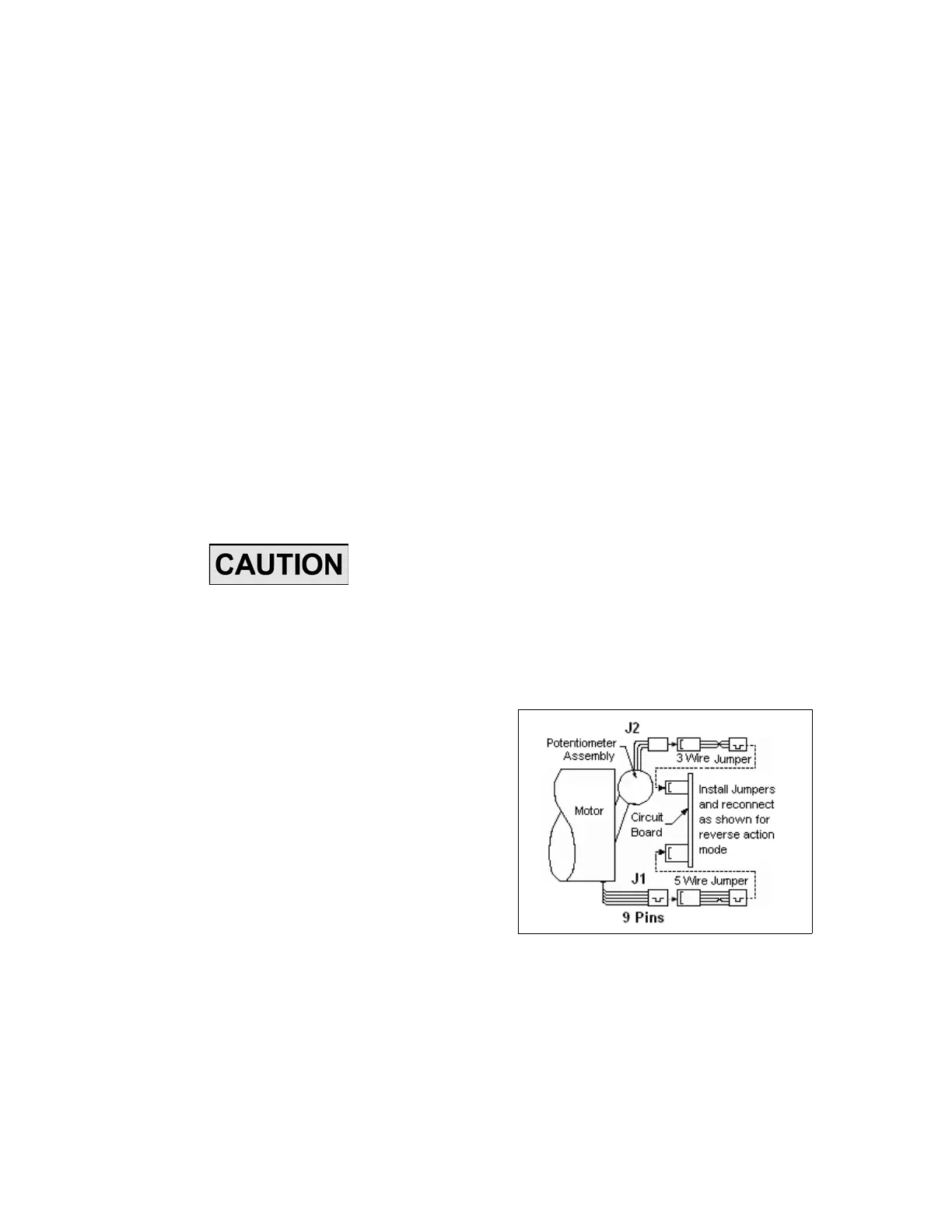
2. Remove power from ECC and remove cover.
3. Install jumper plugs between circuit board and
potentiometer and circuit b oard a nd motor
(Figure 8). Jumper plugs are available from the
factory:
3 wire jumper 0152173200 (J2)
5 wire jumper 40229 (J1)
Figure 8. Jumper Plugs/Action Mode
Conversion.
4. Dis connect ECC fr om pu mp. Remove the four
screws that mount the ECC to the bracket and
carefully remove the ECC from t he pump. On
MaxRoy B pu mps loosen coupling nut (Figure
www.motralec.com / service-commercial@motralec.com / 01.39.97.65.10

 Loading...