18
3. Disconnect ECC from its mounting bracket by
removing four mountin g screws and pulling
unit.
4. Unscrew cover (280) from ECC.
5. Carefully loosen three captive sc rews equally
(do not completely remove screws) and gently
lift PCB from mounting standoffs.
6. Disconnect connectors J 1, J2, J3, J4, and J5
from bottom of PCB.
4.4.2 Installation of PCB
1. Connect connectors J1, J2, J3, J4, and J5 to
bottom of PCB.
2. Place PCB o n thr ee standoffs an d car efully
tighten captive screws. Ensure nylon washers
are on ca ptive screws be tween PCB an d
standoffs.
3. Perform calibration B if board was calibrated at
factory or calibration C if board was not cal i-
brated at factory.
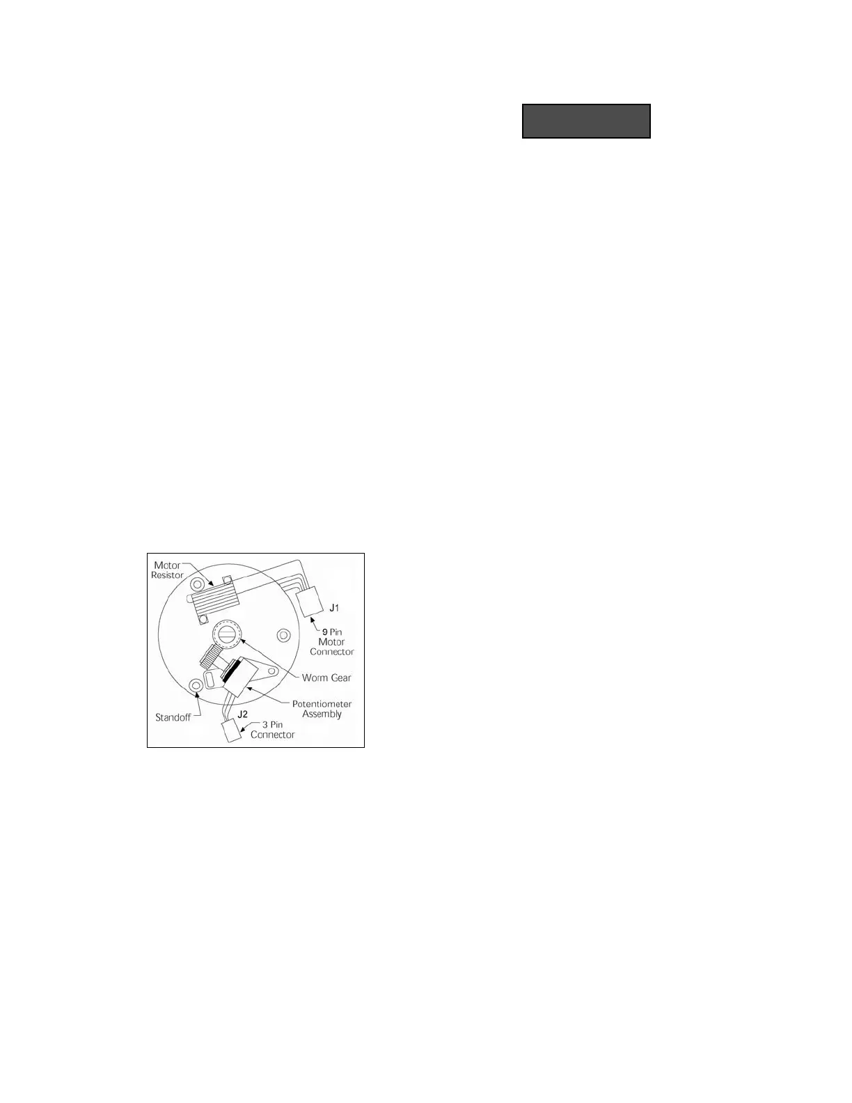
Figure 13. Circuit Board Removed.
4.5 FEEDBACK POTENTIOMETER REPLACE-
MENT
4.5.1 Removal of Feedback Potentiometer
1. Apply power and set pump stroke adjust knob
to 0% settin g or remove powe r and man ually
turn the pump stroke adjust knob to 0% setting.
ALWAYS DIS CONNECT ELECTRICAL
POWER FROM THE PUMP MOTOR AND
ECC BEFO RE PER FORMING AN Y
MAINTENANCE. FAILURE TO FOL LOW
THESE INSTR UCTIONS COULD
RESULT IN DEATH OR SE RIOUS
INJURY.
2. Disconnect electrical power to ECC.
3. Remove PCB (Paragraph 4.4.1).
4. Remove two screws that secure potentiometer/
bracket/gear asse mbly. Re move feed back
potentiometer.
4.5.2 Installation of Feedback Potentiometer
1. Inst all r eplacement po tentiometer a ssembly.
Apply very slig ht pressure and align teeth of
gear to lay inside groves of nylon gear. Do not
force gears together overly tight or allow teeth
to lay on to p of wor m ge ar teeth. Tighten two
retaining screws. There should be slight pres-
sure between gears.
2. Apply a very small amount of lithium grease (if
needed to motor shaft nylon worm gear. Motor
shaft may ha ve gr ease from pr evious ma inte-
nance.
3. Compare wire colors of ne w feedback potenti-
ometer connector to wir e co lors of old fe ed-
back potentiometer co nnector. Whe n p lace-
ment of wire s is dif ferent in stall jum per cabl e
(ordered with ne w fee dback po tentiometer)
between P2 and J2 (Figure 13).
4. Install PCB (Paragraph 4.4.2).
5. Perform calibration A.
4.6 NYLON WORM GEAR REPLACEMENT
4.6.1 Removal of Nylon Worm Gear
1. Apply power and set pump stroke adjust knob
to 0% se tting or remove power and manually
turn the pump stroke adjust knob to 0% setting.
www.motralec.com / service-commercial@motralec.com / 01.39.97.65.10

 Loading...